Charging battery in car/solar

Submitted: Wednesday, Nov 14, 2018 at 14:59
ThreadID: 137466 Views:5067 Replies:11 FollowUps:35
This Thread has been Archived
G,day quick question for the sparkies . got a PX 2012 Ranger with second battery fitted , charging the 2nd battery with the car through a red arc isolator SBI 12 from main battery and also has a solar panel & regulator fitted ( 200w ?) . But no DC DC type charger .
My question is , is this in any way detrimental to the car itself . 2nd part , or the battery if its getting a good charge from the solar when the car is Not running . I normally disconnect the solar when the car is running but is it necessary to disconnect in regards to damaging the vehicle that.
Also with this setup is it possible that for any reason for the second battery to appear not to accept charge from the solar panel at times or would this be a connection problem .
Cheers
Cheers Nick b

Member
My Profile  My Blog  Send Message

Back Expand Un-Read 0 Moderator

Reply By: Phillipn - Wednesday, Nov 14, 2018 at 15:48

Wednesday, Nov 14, 2018 at 15:48
You will not be getting a full charge to your second battery. Once the starter battery is charged the voltage from the smart alternator will drop back.
You need to fit a dc to dc charger.
I have a dc/ dc charger which charges from the motor and solar panels, the battery is on float charge all the time, but drops back when the fridge is in use. the battery charge soon returns to float charge after a short time.
The wiring from the motor to the charger needs to be 6 B& S to eliminate voltage drop.
AnswerID: 622141

Reply By: Gbc.. - Wednesday, Nov 14, 2018 at 15:53

Wednesday, Nov 14, 2018 at 15:53
Have you had the car since new? You can get the smart alternator turned off by a ford dealer and it will revert to a dumb 14.5v feed. No dc charger required once that is done. You won’t damage the panel by leaving it plugged in. Depending on the charge state the reg will slow down to equalisation mode or shut off completely making it look like the battery isn’t charging anymore.
AnswerID: 622142

Reply By: RMD - Wednesday, Nov 14, 2018 at 16:37

Wednesday, Nov 14, 2018 at 16:37
Nickb
If you haven't had the, some call them "smart" alternator feature turned off as suggested above, the alt will be producing ECU regulated voltage all/most the time instead of around 14.4v.
Therefore, if the alt has turned down the main battery voltage, the solar input(if on) being well above that will be directed to the main and the aux battery if solar is connected.. The solar would be trying to make up the shortfall of voltage which the alternator isn't being allowed to create. Whatever WAS in the aux will be given to the main battery especially if the solar is OFF.
It may well be the solar IS charging but because both batteries are linked via a solid connection relay and the solar now inactive, the aux battery will run down to whatever the ECU wants the main to be. That will mean not much remaining in the aux to run a fridge without the aux getting to the discharged point.
Even IF the alt did charge sensible voltage for a while it will never charge the aux to where you need it to be.
You said the solar is disconnected while driving, that ensures the aux will be flat or near to.
A dc dc unit is a power converter and uses two/either inputs to switch an inverter to create the amps and voltage you require. It ensures auto disconnect or non use of whatever is less and not working for you and uses the best input energy source.

With a PX you need one which will sense the low voltage of the ECU alt and that will/should solve the problem and keep the batteries electrically isolated from each other. You should be able to leave the solar on all the time with the present system. It will be if a dc dc is used.
Alternatively
To use the alt when charging enough you may need a BIG diode unit so the alt charge voltage when near to enough will actually charge the aux battery a bit. At present the SB1 12 ensures both way flows which is fighting against you.
AnswerID: 622143

Follow Up By: Member - nickb "boab" - Wednesday, Nov 14, 2018 at 21:43

Wednesday, Nov 14, 2018 at 21:43
QUOTE "It may well be the solar IS charging but because both batteries are linked via a solid connection relay and the solar now inactive, the aux battery will run down to whatever the ECU wants the main to be. That will mean not much remaining in the aux to run a fridge without the aux getting to the discharged point"

this is what i was wondering in sum way ....but then will charge properly at other times ....
Cheers Nick b

Member
My Profile  My Blog  Send Message

0
FollowupID: 894866

Follow Up By: HKB Electronics - Thursday, Nov 15, 2018 at 09:52

Thursday, Nov 15, 2018 at 09:52
The ECU in the car should be maintaining the cars battery in a fully charged condition assuming all is well, therefore even with the VSR linking the two batteries together the aux should not be discharging into the cars battery. If the aux is in a low state of charge it will most likely rob some charge from the cars battery but at a very low rate assuming the smart charge is active.

The solar will as will be of no advantage in charging the aux once the VSR engages.

Lifetime Member
My Profile  Send Message

1
FollowupID: 894877

Reply By: HKB Electronics - Wednesday, Nov 14, 2018 at 17:06

Wednesday, Nov 14, 2018 at 17:06
As GBC wrote, have the smart charge turned off if you haven't and all will be well.

Yes you can leave the solar connected all the time if your using a good quality solar controller.

Lifetime Member
My Profile  Send Message

AnswerID: 622144

Reply By: Peter_n_Margaret - Wednesday, Nov 14, 2018 at 17:16

Wednesday, Nov 14, 2018 at 17:16
1. "Smart" alternators aside, and provided the batteries are compatible with each other in terms of charge voltage requirements, there is no problem having both the alternator and the solar charging at the same time.

2. Provided the voltage drop between the 2 batteries is minimal (ie the cables are BIG enough), both can be fully charged by either source (if input is greater than output). Both should stop charging when the batteries are full. You don't need a DC-DC charger if you get appropriate voltage to the second battery from the alternator, only if the voltage drop is too high.

I do exactly this. There is 600W of solar, 460Ah of house batteries, a 120Ah AGM crank battery and an 80A alternator with an output of 14.3V. If I manually LOCK the 2 way 200A VSR, eventually the solar input voltage will exceed the voltage output of the alternator and the alternator will shut down. This kills my tacho and the charge light on the dash comes on. I know then that everything is fully charged and unlock the VSR. Alternately, it can just run on auto, or be left open.

Cheers,
Peter
OKA196 motorhome
AnswerID: 622145

Follow Up By: RMD - Wednesday, Nov 14, 2018 at 17:28

Wednesday, Nov 14, 2018 at 17:28
G'Day Peter
Does your alternator have a, centre of stator connection, which supplies 1/2 battery voltage to some electrical items?
The charging sensing must be taken from there or near the exiter diodes it seems.
0
FollowupID: 894863

Follow Up By: Peter_n_Margaret - Wednesday, Nov 14, 2018 at 17:39

Wednesday, Nov 14, 2018 at 17:39
No idea actually :) The tacho signal comes from the alternator too.
All I know is that it works a treat and has done so for 15 years.
I usually only lock the VSR when the house batteries are well down and I don't think there is enough sun to get them fully charged again from the solar alone while driving.
I have checked the house battery charge rate and have seen up to 70A (depending on state of charge of the house batteries, that drops off as the house batteries come up) going in from the alternator PLUS 30A going in from the solar all at the same time (total 100A charge rate).
I have also used the solar to charge the cranking battery when not driving if I have left the lights on or something stupid.
Cheers,
Peter
OKA196 motorhome
1
FollowupID: 894864

Reply By: Frank P (NSW) - Wednesday, Nov 14, 2018 at 17:34

Wednesday, Nov 14, 2018 at 17:34
Nick,

I have a 2014 BT50. It doesn't have the so-called Smart Charge system that your Ranger has. Nevertheless I chose to use a DC-DC charger for the aux battery in the canopy.

My approach was to use a smart isolator to power a very heavy duty buss (0 gauge) that powers everything at the back. I can also manually parallel the batteries in the event of a flat crank battery and for winching. You don't have to do that in which case 6 gauge would be sufficient.

Here's a circuit diagram of my setup. It works a treat.

Your SBI12 replaces my VS12 and 300 amp solenoid in the engine compartment so that simplifies things up front.

In the canopy I have chosen to fit a change-over relay so that when the engine is running the fridge is powered by the crank battery/alternator, and when the engine is off the fridge is powered from the aux battery. I did this because it is better for the DC-DC charger to be charging a battery with no load on it, and it's easy to do, but certainly not compulsory.

Cheers


FrankP

Lifetime Member
My Profile  My Blog  My Position  Send Message
Moderator

AnswerID: 622146

Reply By: 9900Eagle - Wednesday, Nov 14, 2018 at 18:54

Wednesday, Nov 14, 2018 at 18:54
Once you have the smart charge turned off, make sure the second battery earth goes to the bolt on the body adjacent the battery, next thing is the change voltage won't stay static at 14.4v, it will alter due to the alternator being temperature compensated. Mine varies from 14.5 volts down under 13.5 volts as the ambient temp rises.

Can't help with solar as I never have both connected while engine is running.
AnswerID: 622147

Follow Up By: Member - nickb "boab" - Wednesday, Nov 14, 2018 at 21:00

Wednesday, Nov 14, 2018 at 21:00
I don't know if the smart charge is off or not but mine varies in voltage as you have mentioned here , on start up i.e in the morning voltage shoots up to 14.7 ?? on my gauge (plug in type ) them after running for a while drops back mid 13.3

my vehicle is a steel tray back , battery is mounted on chassis , heavy earth cable to the chassis & tray but not to the cab .

cheers
Cheers Nick b

Member
My Profile  My Blog  Send Message

0
FollowupID: 894865

Follow Up By: 9900Eagle - Thursday, Nov 15, 2018 at 04:43

Thursday, Nov 15, 2018 at 04:43
Nick, the earth from the second battery should be all good bolted to the chassis as long as the paint under the lug has been removed.

I would think the smart charge is turned off as with it on it will let your battery go down as low as 12.2 volts before kicking in and charging.
2
FollowupID: 894870

Reply By: Member - nickb "boab" - Wednesday, Nov 14, 2018 at 21:33

Wednesday, Nov 14, 2018 at 21:33
thank you all for the swift replies & answering the main question (re damage)
I don't know if the smart charge is off or not as i got the vehicle S/H ex government work car. but mine varies in voltage as has been mentioned here , on start up i.e in the morning voltage shoots up to 14.7 ?? on my gauge (plug in type ) them after running for a while drops back 13.3 av
when the solar is plugged in and vehicle not running sits around the mid 13's with small fridge in the back .the 2nd battery is a blue century (marine ??)

i have found on occasions when camping that the 2nd battery doesn't look like its getting any charge from the solar even when i have connected a second panel... but the panel does charge another batteries ..... which has been very confusing ???
still re reading some of the replies cheers
Cheers Nick b

Member
My Profile  My Blog  Send Message

AnswerID: 622149

Follow Up By: Gbc.. - Thursday, Nov 15, 2018 at 07:53

Thursday, Nov 15, 2018 at 07:53
As I stated before, sitting at mid 13’s the battery will be fully charged and and solar controller will go into ‘float’ and supply very little power.
Charging is all about what a battery wants to accept, not about what you want to stuff down its neck. Hope that makes sense as it is an important concept.
Attach other batteries which haven’t been charged as well and the panel will start charging them.
All in all it sounds like you have a decent system which is working well. There’s a fuse you can pull to disable the smart alt too but I have forgotten which one it is. I’ve had a PX for 5 years.
1
FollowupID: 894872

Follow Up By: Member - nickb "boab" - Thursday, Nov 15, 2018 at 22:10

Thursday, Nov 15, 2018 at 22:10
with out going to Ford is there any way to knowing if the smartcharge is disconnected or not ?
Cheers Nick b

Member
My Profile  My Blog  Send Message

0
FollowupID: 894894

Follow Up By: 9900Eagle - Friday, Nov 16, 2018 at 04:40

Friday, Nov 16, 2018 at 04:40
Yes, if you have a ultra gauge or scan gauge you can read the voltage on them. If the smart charge is still active you can see the voltage change as you accelerate or coast. The smart charge will only charge when the vehicle is under light load, going down a hill breaking or if the battery voltage gets to low. From memory it will let the battery get down to around 12.2 volts before it charges all the time.

With smart charge disconnected you will see the voltage remain fairly constant all the time, this voltage will change due to ambient temperature but will not drop below around 13.2 volts on a hot day. Most of the time it will be between 14.5 volts and 13.8 volts.
2
FollowupID: 894897

Follow Up By: nickb - Friday, Nov 16, 2018 at 20:45

Friday, Nov 16, 2018 at 20:45
If your voltage is fluctuating as you describe then smart charge is activated. As mentioned above if it has been deactivated it will not go much lower than 14V if at all.
Mine does similar to yours and smart charge has not been deactivated. It usually puts out 14.6V in the morning and tapers off to 13.6V after a while.
1
FollowupID: 894923

Follow Up By: Member - nickb "boab" - Saturday, Nov 17, 2018 at 10:19

Saturday, Nov 17, 2018 at 10:19
Ok thanks : by turning off smart charge what effect is that likely to have on charging the second battery in this situation . Is it likely to put more charge for longer periods into the auxiliary battery ?
And how is this different from what a DC DC charger would do in regards to charging the auxiliary battery .
Cheers Nick b

Member
My Profile  My Blog  Send Message

0
FollowupID: 894934

Follow Up By: Frank P (NSW) - Saturday, Nov 17, 2018 at 11:55

Saturday, Nov 17, 2018 at 11:55
Most auxiliary batteries are deep cycle. Many (but not all) deep cycle batteries have charging regimes not necessarily provided for by the alternator. For example, manufacturers may specify a current limitation or a high absorption voltage requirement, or both.

Many deep cycle batteries have a max recommended charge current of 10 to 15% of C20 capacity. So a 100Ah battery may have a specified max charging current of 10 to 15 amps. An alternator won't know that and may pump in 30 or 40 amps (cabling permitting!).

Depending on the chemistry, the absorption voltage may be quite high. I had one that specified 15.5 volts. An alternator won't know that either and will probably only supply around 14.2 volts. In those circumstances the battery will not get a full charge.

A well chosen DC-DC charger will have correct settings for your chosen auxiliary battery. Most have fixed settings such as Flooded, Gel, AGM, Calcium and sometimes Lithium, which do the job well. The best ones have a solar input and are programmable so they can be exactly tailored to the battery manufacturer's requirements and charge consistently whether the source is alternator or solar. Enerdrive's DC2DC 40A Plus is one of those. (Link.)

You can ignore the manufacturer's specs and use a direct alternator charge. You will probably get a faster charge which may be important if your touring habits dictate reduced driving times, but it may come at the cost of overall battery life.

Alternatively to the DC-DC charger, choose a deep cycle battery that is designed to accept a plain vanilla alternator charging profile.
Cheers
FrankP

Lifetime Member
My Profile  My Blog  My Position  Send Message
Moderator

3
FollowupID: 894940

Follow Up By: HKB Electronics - Saturday, Nov 17, 2018 at 16:07

Saturday, Nov 17, 2018 at 16:07
I wouldn't say a well chosen DCDC will any better settings than the alternator, if we look at the ctek, if they haven't changed it since I last looked maximum charge voltage was 14.4V from memory.

If we look at the Redarc they claim charging algorithms to suit specific chemistries, when you read the manual this becomes you can select the maximum charge voltage at 14.6, 15V or 15.4V doesn't sound like any amazing charge algorithm to me. These two chargers are what most buy.

If your going to use an AGM that only accepts low charge of 10%-15% then in the case of OP with one aux battery which is most likely around 100Ah why would you spend the money on a 40A charger, granted though having user parameters could be good.

Lifetime Member
My Profile  Send Message

0
FollowupID: 894948

Follow Up By: Frank P (NSW) - Saturday, Nov 17, 2018 at 17:57

Saturday, Nov 17, 2018 at 17:57
If you already have a battery that requires absorption at 15.4V to fully charge it and chose a charger with a max voltage of 14.4V, then the charger is not well chosen, is it?

Conversely, If you already have the charger, then choosing a battery that requires an algorithm that the charger cannot deliver would also not be a wise choice.

"If we look at the Redarc they claim charging algorithms to suit specific chemistries, when you read the manual this becomes you can select the maximum charge voltage at 14.6, 15V or 15.4V doesn't sound like any amazing charge algorithm to me. These two chargers are what most buy."

Redarc CLAIM charging algorithms...
(selectable max voltage) doesn't sound like any amazing charge algorithm to me.

Sounds like you think Redarc is cheating.

Are you saying that all that's happening in the Redarc chargers is supply voltage in and either 14.6, 15 or 15.4 volts out - nothing else? Ie, Redarc's $500 box is no better than your $50 diode that tricks the alternator into delivering a higher voltage? I think there's more to it than that, don't you?

Cheers
FrankP

Lifetime Member
My Profile  My Blog  My Position  Send Message
Moderator

0
FollowupID: 894950

Follow Up By: HKB Electronics - Saturday, Nov 17, 2018 at 18:04

Saturday, Nov 17, 2018 at 18:04
"If you already have a battery that requires absorption at 15.4V to fully charge it"

The above statement is incorrect, just about every charger on the market only charge to from around 80% SOC to 95% SOC during the absorption stage , the battery is brought up to a 100% SOC during the float stage at around 13.5V-13.8V for most chargers. You do not need 15.4V to fully charge the battery.

Redarc's charger is a basic 3 stage charger, limits charge to its maximum rated output so it doesn't burn itself out, then reverts to constant voltage charging at its maximum allowable charge voltage till current drops to around 500ma then goes to float charge. If you call that a fancy charge algorithm then so be it. Worth paying $500 for, up to the user to decide that.

As for the product I manufacture I fail to see what it has to do with this discussion which is about turning off the smart charge function in the PX. Turning it off will give a much improved rate of charge without the need for a DCDC charger as a lot of PX owners running simple VSR setups will agree with.

Lifetime Member
My Profile  Send Message

1
FollowupID: 894951

Follow Up By: garrycol - Saturday, Nov 17, 2018 at 19:22

Saturday, Nov 17, 2018 at 19:22
Yes the charging voltage for most batteries is the highest voltage it can be charged at, not the specific charge it is to be charged at. At a lower voltage level - say 13.7v instead of 15.4v the battery will just take a little longer to charge but it will still charge to 100%.
1
FollowupID: 894952

Follow Up By: Frank P (NSW) - Saturday, Nov 17, 2018 at 22:57

Saturday, Nov 17, 2018 at 22:57
HKB

"If you already have a battery that requires absorption at 15.4V to fully charge it"

"The above statement is incorrect, just about every charger on the market only charge to from around 80% SOC to 95% SOC during the absorption stage , the battery is brought up to a 100% SOC during the float stage at around 13.5V-13.8V for most chargers. You do not need 15.4V to fully charge the battery."

"If you already have a battery that requires absorption at 15.4V to fully charge it" is not a statement. It is a conditional phrase that says nothing by itself. You've completely missed the point of the whole sentence that it was part of and built a fallacious argument around an out-of-context partial quote. The key word is "IF".

With respect, you need to do some research. Your description of how multi stage chargers work is simply wrong, quite wrong.

Some chargers may have more than the three basic stages - eg Ctek with a preliminary desulphation stage and a fifth pulsed stage.

But most multi stage lead-acid DC-DC chargers use three basic stages. The first charges at constant current (max for the unit or whatever is the programmed max in programmable types) until the absorption voltage setpoint is reached. This is the BULK stage (not absorption). It gets the battery to about 80% SOC. The target absorption voltage, often referred to as the maximum voltage (Garrycol, please note), is typically in the range of 14.1 to 14.4 but some may fall outside this range. As I said earlier, I had one that was 15.5.

The charger then holds the battery at that voltage while the current gradually reduces. THIS is the Absorption stage, where the battery gets the remaining 20% or so of charge, NOT the initial 80%.

When the current falls in the absorption phase to a pre-determined (or perhaps programmable) figure, or after a set time, the charger enters Float stage. Float is a maintenance stage for maintaining a battery that is fully charged by the preceding two stages. Garrycol, again, please note.

The above can be found in any reference material. Link Link Link
(The last link uses different terminology for the stages, but they are the same)
A similar description, or a diagram similar to the one below can also be found in the user manual of most DC-DC chargers, including the Redarc products, the Ctek and Enerdrive's DC2DC that have been mentioned in this discussion.

I mentioned the product you manufacture because in Followup 7 above you wrote

"If we look at the Redarc they claim charging algorithms to suit specific chemistries, when you read the manual this becomes you can select the maximum charge voltage at 14.6, 15V or 15.4V doesn't sound like any amazing charge algorithm to me."

The way you have written it, whether you meant it or not, clearly says that you think Redarc's chargers are nothing more than simple voltage step-up devices, in which case a rhetorical comparison between your device which does just that and the much more expensive Redarc is not inappropriate.

garrycol
This followup is in response to you also.

Here's a graph from Wikipaedia (one of the above links) of three stage charging and effect on SOC.
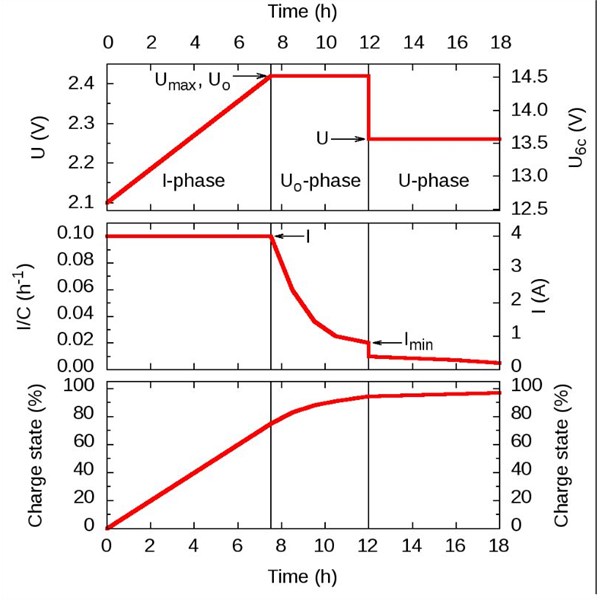
FrankP

Lifetime Member
My Profile  My Blog  My Position  Send Message
Moderator

0
FollowupID: 894954

Follow Up By: HKB Electronics - Sunday, Nov 18, 2018 at 11:31

Sunday, Nov 18, 2018 at 11:31
Also with respect you need to do some more research, on how chargers actually work and stop relying on the mistruths in the glossies. the Redarc and ctek bulk charge stage as you refer to it is nothing more than the charger protecting itself from overloading. For the 20A redarc charge it is set at a maximum of 20A for the 30A version it is 30A , for a 40A charger it will be 40A etc, the charger will maintain that current till the charge current drops below the maximum current setting allowed, it will then revert to constant voltage charging. There is nothing smart about that it is just a protection stage of the charger now called absorption stage to make the charge seem smart. Yes you can use the charger to limit the charge if needed, and some chargers allow you to set the current, but why would you buy a 40A charger then set it to 20A?

The absorption stage is a constant voltage charging stage same as used by an alternator which brings the battery to certain stage of charge in a safe way, ie the current reduces and the voltage is held at a fixed voltage to prevent excess heat being generated in the battery. This stage does not fully charge the battery, it only continues till a predeterimed current level is reached. As far as I have seen the current level is the same in all settings of the redarc chargers, the only thing that changes is the max voltage, I don't see any fancy algorithms in use specific to certain chemistries. Same for ctek chargers. Same for the Enerdrive units to you can set the maximum charge voltage, the charge current and when it stops charging. Changing the chemistry only changes these settings if you call this a fancy charging algorithm then so be it. Mind you different charger manufactures have differing opinions of what are the best setting for different types of batteries, they can't even agree on that.

As above the absorption stage does not bring the battery to full state of charge, it cant, the battery is being forced charged at high rate, even if it contnued till the charge current dropped to zero the battery still wouldn't be fully charged, as soon as the charge voltage reduces the batteries internal resistance will drop and it will start charging again. Your graph above clearly shows this, you can see where the SOC continues to rise once the charger switches to the float stage. As you like quoting the web here is some info of the web for you to absorb:

"Stage 2 | Absorption Charge
Smart chargers will detect voltage and resistance from the battery prior to charging. After reading the battery the charger determines which stage to properly charge at. Once the battery has reached 80%* state of charge, the charger will enter the absorption stage. At this point most chargers will maintain a steady voltage, while the amperage declines. The lower current going into the battery safely brings up the charge on the battery without overheating it.
This stage takes more time. For instance, the last remaining 20% of the battery takes much longer when compared to the first 20% during the bulk stage. The current continuously declines until the battery almost reaches full capacity."

"Stage 3 | Float Charge
Some chargers enter float mode as early as 85% state of charge but others begin closer to 95%. Either way, the float stage brings the battery all the way through and maintains the 100% state of charge. The voltage will taper down and maintain at a steady 13.2-13.4 volts, which is the maximum voltage a 12 volt battery can hold. The current will also decrease to a point where it's considered a trickle. That's where the term "trickle charger" comes from. It's essentially the float stage where there is charge going into the battery at all times, but only at a safe rate to ensure a full state of charge and nothing more. Most smart chargers do not turn off at this point, yet it is completely safe to leave a battery in float mode for months to even years at a time."

The other point to note is batteries don't need three stage charging, they were and still are happily using single stage chargers ie your car battery. It is quite slick how the manufactures of chargers have sold the limitations of their products as being beneficial for the battery, chargers need the first two stages to work. The third float stage is really only required if your going to have the charger connected 24/7. As for the desulphation and pulse charge stages, they are gimmick stages and can be put into the same category as electronic rust protection systems.

Batteries both in the past and present have been quite happily charged using basic single stage float chargers, most large commercial installations using lead acid batteries still do it this way with battery banks that cost hundreds of thousands of dollars.

This is not adding anything useful to the discussion, it is just the usual VSR versus DCDC charger debate which has already been done to death, if you want to spend heaps on a device that others few it any advantages them go for it.

Lifetime Member
My Profile  Send Message

0
FollowupID: 894956

Follow Up By: Frank P (NSW) - Sunday, Nov 18, 2018 at 12:24

Sunday, Nov 18, 2018 at 12:24
I don't think your quotes from the web say anything different to those I linked to, so I don't get whatever point you're trying to make.

In regard to your first paragraph, part of it another out of context argument, go back and re-read my Followup #6. I never recommended buying a 40A charger and winding it down to 20A. I presented the 40A Enerdrive as an example of a programmable charger that also has solar input.
.
A well chosen charger would be one where its parameters (max current and voltage setpoints) match those of the target battery. Eg, for a battery that likes 15A, buy a 15A charger. I never said otherwise.

"This is not adding anything useful to the discussion, it is just the usual VSR versus DCDC charger debate which has already been done to death"

I agree. Time to quit
FrankP

Lifetime Member
My Profile  My Blog  My Position  Send Message
Moderator

1
FollowupID: 894957

Reply By: noggins - Thursday, Nov 15, 2018 at 10:28

Thursday, Nov 15, 2018 at 10:28
My 2012 PX has a similar system with the exception I don't use a VSR , just a 150A 12V relay run from an ignition controlled small 40A relay tha switches power to other appliances as well.

I have 2x100AH batteries in the tub and a 140W solar on the canopy.
The smart charger is turned off and I get a constant 14.2V at all points.

My solar is set to float at 13.9V and powers an Engel in the back 24/7 @ -2deg .

Both Alt and solar are connected to the batteries and the solar keeps the batteries on float ( or near that ) when not driving.

So when driving All the Batteries get 14.2V and when parked get the solar @ 13.9V
It's been this way for a few years now and has never caused any problems.

Your system will loose a bit of voltage at the VSR but the tub batteries are well in a good charge rate and if the solar charge / float is set properly the alt will be the main source of charging when driving and the solar will be backing it up and keeping it all nice.
AnswerID: 622156

Reply By: Peter_n_Margaret - Thursday, Nov 15, 2018 at 12:32

Thursday, Nov 15, 2018 at 12:32
For many years my son operated the simplest dual battery & solar set up I have come across.
The second battery was simply in parallel with the crank battery. No VSR, no DC-DC, no switch or anything else. Nothing. Just one big battery.
The solar charged both. The alternator charged both. No discrimination.

All loads were powered via a low voltage cut out that switched them off before the combined batteries got too low to start the engine (and that can be quite low).
The advantage was (apart from ultimate simplicity) both batteries were always available to power the loads or start the engine, so his available capacity for accessories was always much higher than most other arrangements and "losses" were much reduced..

Adjustable range low voltage cut outs are readily available.
Cheers,
Peter
OKA196 motorhome
AnswerID: 622158

Follow Up By: Member - Boobook - Saturday, Nov 17, 2018 at 07:19

Saturday, Nov 17, 2018 at 07:19
Simple and effective.

The issue comes down to what you are putting at risk when you use more than the usual power and what are using.

If you have a fridge, then the normal split battery system puts the long term battery life at risk when you can't charge and go over the normal discharge amount but protects the ability to start the engine like normal. However, it does protect the food and safety in the fridge.

The method you describe protects the long term life of the batteries,, but puts food safety at risk.

Of course if you don't have a fridge then that's not an issue.

There is not magic bullet.


0
FollowupID: 894928

Follow Up By: Peter_n_Margaret - Saturday, Nov 17, 2018 at 08:00

Saturday, Nov 17, 2018 at 08:00
I suggest that the food risk is in fact lower.
You have exactly the same charge facilities available, but more battery capacity.
Cheers,
Peter
OKA196 motorhome
0
FollowupID: 894929

Follow Up By: Member - Boobook - Saturday, Nov 17, 2018 at 08:14

Saturday, Nov 17, 2018 at 08:14
But the battery disconnect stops you using that capacity. That's what it's there for.

You can over ride that, but same for both solutions, and in that case you have exactly the same capacity.

0
FollowupID: 894930

Follow Up By: Peter_n_Margaret - Saturday, Nov 17, 2018 at 08:41

Saturday, Nov 17, 2018 at 08:41
The battery disconnect does not have to happen until both are 80% flat & that point is adjustable, unlike a VSR which tend to isolate much earlier (and need to).
It does not take much left from 2 batteries combined to start an engine.
Cheers,
Peter
OKA196 motorhome
0
FollowupID: 894931

Follow Up By: Member - Boobook - Saturday, Nov 17, 2018 at 08:46

Saturday, Nov 17, 2018 at 08:46
Good ol' electrical / battery threads hey Peter?

If the disconnect waiting till both batteries are 80% flat then I'd suggest that you are harming both batteries and shortening their life. I would rethink that strategy.

Anyway it's not my business. I certainly would not recommend to anyone else to do that. though.
0
FollowupID: 894932

Follow Up By: Peter_n_Margaret - Saturday, Nov 17, 2018 at 11:21

Saturday, Nov 17, 2018 at 11:21
"Good ol' electrical / battery threads hey Peter?"
Absolutely :)
We are getting off track now, but the belief that taking deep cycle batteries below 50% damages them is an urban myth.
Yes, you get less cycles, but the appreciation of a battery's life is best measured in total power delivered, not cycles.

That should keep this going for a bit longer..... :)

Cheers,
Peter
OKA196 motorhome
0
FollowupID: 894936

Follow Up By: Member - Boobook - Saturday, Nov 17, 2018 at 12:52

Saturday, Nov 17, 2018 at 12:52
"That should keep this going for a bit longer..... :)"

You're a braver man than I am gunga din.
1
FollowupID: 894942

Follow Up By: HKB Electronics - Saturday, Nov 17, 2018 at 15:52

Saturday, Nov 17, 2018 at 15:52
Agree with you Peter, it is through put that counts as discussed on another forum.

Discharging to 50% may appear to give longer life when looking at life cycles versus depth of discharge graphs but when you look at Ah in Ah out there is practically no difference in battery life with 50% DOD compared to 80% DOD.

Lifetime Member
My Profile  Send Message

0
FollowupID: 894947

Follow Up By: Peter_n_Margaret - Saturday, Nov 17, 2018 at 17:43

Saturday, Nov 17, 2018 at 17:43
"......there is practically no difference in battery life with 50% DOD compared to 80% DOD."

Spoil sport :) :) :)

Cheers,
Peter
OKA196 motorhome
0
FollowupID: 894949

Follow Up By: Phil G - Saturday, Nov 17, 2018 at 19:38

Saturday, Nov 17, 2018 at 19:38
I sense we're coming full circle here :-) I've also recommended different dual battery setups for my son and daughters

My son has an FJCruiser - we fitted a second battery tray but both his battery trays only fit 10" batteries - so he has a pair of ex-200series cranking batteries in parallel without an isolator and low voltage cutout. Works great for him

One daughter has a 120Prado V6 and for her I recommended a single oversize battery and low voltage cutout, so she has a 100Ah Exide Extreme cranking battery and runs the fridge off that as required. The petrol motors crank easily.

As for me, I'd rather something better - so like the DC-DC charger with roof solar input to the aux battery.
0
FollowupID: 894953

Reply By: Allan B (Sunshine Coast) - Sunday, Nov 18, 2018 at 15:08

Sunday, Nov 18, 2018 at 15:08
.
As I said a few weeks back..... this forum "Just needs a good Battery Thread to get things moving."

Worthy of becoming an Olympic Games sport?
Or "Battery Battles" on Channel Ten?

Trouble is... no-one would agree on the rules.
I'll just sit up in the stand and be entertained. lol
Cheers
Allan

Member
My Profile  My Blog  My Position  Send Message

AnswerID: 622203

Follow Up By: Member - nickb "boab" - Sunday, Nov 18, 2018 at 17:01

Sunday, Nov 18, 2018 at 17:01
I think i'll buy a honda generator , will be easier to understand..... LOL :D

Allan would you like a crack at one of my question ?

i have found on occasions when camping that the 2nd battery doesn't look like its getting / accepting any charge from the solar even { when i have connected a second panel.} Note: but most of the time works just fine .
Note: this panel does charge another battery perfectly well .

The setup is > redarc isolator SBI 12 splitting the two batteries , single wire going at the auxiliary via the bsi 12 . regulated solar panel .
Cheers Nick b

Member
My Profile  My Blog  Send Message

0
FollowupID: 894961

Follow Up By: Allan B (Sunshine Coast) - Sunday, Nov 18, 2018 at 18:18

Sunday, Nov 18, 2018 at 18:18
.
Hi Nick,

I have no desire to join a bunfight but as you asked so nicely......

From the information available it does sound rather like a poor connection or an intermittent fault but diagnosing it from the information so far would be largely guesswork. If you can answer the following questions it may help at pinning it down......

1) How have you determined that "the 2nd battery doesn't look like its getting / accepting any charge from the solar"?

2) You say "even when I have connected a second panel". Is this 'second panel' connected together with the first panel or on its own? If connected together, how, and to where, is it connected?

3) Does the "single wire" from the SBI-12 connect directly to the Aux Battery positive post, and does this battery's negative connect directly to the chassis?

4) Does the positive output from the solar regulator connect to the Aux battery's positive terminal and does the regulator negative connect directly to battery negative or chassis?

5) Are there any plug/sockets or other junctions in the cable from the solar panel to the regulator?

6) Does the Aux Battery charge satisfactorily from the alternator via the SBI-12 when you are driving?

7) Once fully charged, does the Aux Battery provide adequate supply to your accessory load (fridge etc) when at camp?


Cheers
Allan

Member
My Profile  My Blog  My Position  Send Message

0
FollowupID: 894963

Follow Up By: Member - nickb "boab" - Sunday, Nov 18, 2018 at 21:33

Sunday, Nov 18, 2018 at 21:33
thanks Allan .
Q 1 ...volt meter stays the same or goes down , this is when vehicle stationary .

Q 2 the second panel also regulated with alligator clips straight to auxiliary battery

Q3 both yes

Q 4 connected via anderson plugs straight to battery terminals , this is so i can connect different things together I.E i can connect camper trailer solar when touring

Q5 yes anderson

Q 6 yes

Q 7 90 % of the time yes but this is where the problem is , when at camp some time only has 12.2 v for example & no sign of improvement .

It appeared to me that the solar"s x 2 must think its fully charged ?? I have done the usual things checking all connection making sure its not that ....Two completely different setup of charging & both doing the same thing .....

I connected the other portable solar panel to the camper battery & it goes up straight away .

The lights on the solar reg say connected , they are a basic reg lights & volt gauge . in summing up the set up works fine for most of the time . just a few time it has done this & only when camping ....
Cheers Nick b

Member
My Profile  My Blog  Send Message

0
FollowupID: 894966

Follow Up By: Allan B (Sunshine Coast) - Monday, Nov 19, 2018 at 00:22

Monday, Nov 19, 2018 at 00:22
.
Nick,

Thank you for those concise responses.

As the aux battery charges OK from the SBI it seems that the battery is OK.

I can only conclude that there is either an intermittent fault in the panel itself or the solar regulator, or there is a bad connection possibly in an Anderson plug.

Suggest you unplug and inspect each Anderson.... look to see if each contact pin is in the correct way with the curved tip of the pin tucked closely behind the lip of the plastic housing. Also pull hard on each wire entering the Anderson to ensure that the wire is firmly crimped or soldered to the pin. Don't assume that it "looks OK", tug on it to be sure. This will also ensure that the pin is properly latched onto the pressure spring and that there is in fact a spring in place.
Do the "tugging exercise" on any other cable connection points too. If you have any soldered or crimped lugs they could be at fault even if they appear to be OK.
Also check the soundness of the regulator terminals.... that the cable is fully inserted and that the terminal screws are tight. Do the "tug test" here too.

It is suspicious that the "second" solar panel and regulator work OK when connected to the camper battery, yet not when connected to the aux battery. Connecting two solar panels, each with a regulator, in parallel can sometimes cause mal-operation of the regulators.

If you can catch the moment when the system is in its failure mode and measure the voltage at the outgoing "battery" terminals of the regulator, and compare that to the voltage measured at the battery terminal posts, then it may throw some light on the problem.

If the the system "works fine for most of the time" then it is most likely a dodgy connection somewhere, even within the solar panel.

That is about the best I can offer mate.
Cheers
Allan

Member
My Profile  My Blog  My Position  Send Message

0
FollowupID: 894969

Follow Up By: Member - nickb "boab" - Monday, Nov 19, 2018 at 06:20

Monday, Nov 19, 2018 at 06:20
If we considered that the wiring connections from solar panel to battery were fine then the answer maybe in either the regulator from the solar panel or the sbi 12 is somehow confusing the regulator possibly ?? I would imagine that the SBI has switch the main battery off at this stage and is only charging the auxiliary battery??
What really puzzles me is when I connect the other solar panel which I know is charging does exactly the same thing . Next time I will disconnect the original solar panel and connect the other just to double check .
It is possible that it does it more times then I think as I cannot monitor it 24 hours a day ( the fridge lives in the back and is on 24/7 ) & only are aware it does this when camping cause we are keeping a close watch on the conditions of the fridge. Thanks very much for your input & appreciate your time and I shall try these things you have suggest .
Cheers Nick b

Member
My Profile  My Blog  Send Message

1
FollowupID: 894970

Follow Up By: Allan B (Sunshine Coast) - Monday, Nov 19, 2018 at 10:33

Monday, Nov 19, 2018 at 10:33
.
Well Nick, my established form of troubleshooting electrics is to not "consider" or assume ANYTHING but to inspect and test logically and progressively. Only in that way can you eliminate where Mr Murphy may have hidden the fault. But unfortunately 'intermittents' do not play by the rules!

You have said that the alternator "charges satisfactorily via the SBI-12" so there is no problem there and in any case it will not "confuse the regulator". Bear in mind though that if the alternator has raised the aux battery to full charge then the solar regulator will "see" this full charge and cease contributing.

As the alternator is reliably charging the aux battery and the load on that battery is being supplied, it would seem that the battery post connections (clamp or stud) are OK but check them anyway.


Cheers
Allan

Member
My Profile  My Blog  My Position  Send Message

1
FollowupID: 894972

Sponsored Links