Ohmmeter
Submitted: Wednesday, May 09, 2018 at 08:51
ThreadID:
136666
Views:
4685
Replies:
8
FollowUps:
16
This Thread has been Archived
Deejay
Allan (sunshine coast) I hope you read this. On a recent weekend
camping trip I got to test out my solar panel which is now wired in parallel (thanks to those who advised in previous posting). The 20 amp analogue meter did not deflect at all so we assumed it is either broken or I had done something wrong in rewiring the panels. Then we hooked a multi meter into the circuit and it showed 1.6A. Does this sound right? Could this low charge rate be because the battery was almost fully charged after the car trip? Or do I have a problem? It would also appear that I will have to change the ammeter for one of a lower scale. Can anyone advise please? Thanks, Deejay.
Reply By: HKB Electronics - Wednesday, May 09, 2018 at 09:06
Wednesday, May 09, 2018 at 09:06
What was the battery voltage?
AnswerID:
618745
Follow Up By: Deejay - Wednesday, May 09, 2018 at 11:16
Wednesday, May 09, 2018 at 11:16
12.7 volts. 120 watt panel.
FollowupID:
890848
Follow Up By: HKB Electronics - Wednesday, May 09, 2018 at 12:41
Wednesday, May 09, 2018 at 12:41
Charge current will be dependent on the solar panel and state of charge of he battery.
If the battery is showing 12.7V it would appear the panel is providing very little charge as you have monitored. Was the panel in
bright sunshine?
You indicate you have wired the panel in parallel but write 120W panel, do you have two 60W panels?
What are the specs of the panels?
FollowupID:
890851
Follow Up By: Deejay - Wednesday, May 09, 2018 at 14:18
Wednesday, May 09, 2018 at 14:18
Don't have the panel specs on me as I'm at work but it is a 12V, 120W folding panel so I assume it is 2 x 60W. And yes, it was in full sun when tested.
I'm thinking the charge rate had been cut right back by the regulator as the battery was nearly still at full charge.
FollowupID:
890852
Follow Up By: HKB Electronics - Wednesday, May 09, 2018 at 15:06
Wednesday, May 09, 2018 at 15:06
I don't think that would be the case, most regulators will go revert to float charging around around 13.5V, 12.6V is way below a float setting, sounds more like it is not charging.
FollowupID:
890860
Reply By: Member - peter_mcc - Wednesday, May 09, 2018 at 09:44
Wednesday, May 09, 2018 at 09:44
Most new multimeters have a fuse in the current circuit - I'm not sure about your old analogue one but it may have one too. Check the fuse isn't blown!
I can't remember the other thread - what is the voltage/current rating of the panels?
AnswerID:
618746
Follow Up By: Deejay - Wednesday, May 09, 2018 at 11:18
Wednesday, May 09, 2018 at 11:18
No, the analogue meter is permanently hard wired, in-line inside the car. The panels are 12V, 120W (total). The test meter was a digital multimeter.
FollowupID:
890849
Reply By: Member - Racey - Wednesday, May 09, 2018 at 10:23
Wednesday, May 09, 2018 at 10:23
The charging current will be very dependent on the wattage and voltage of the panels. Not to mention the state of the battery and of the amount of sunshine.
Does your 20 amp meter also show discharge current, I.E. centre Zero ? If so, don't change the meter. If not I would be inclined to fit a digital meter.
AnswerID:
618748
Follow Up By: Deejay - Wednesday, May 09, 2018 at 11:20
Wednesday, May 09, 2018 at 11:20
Thanks Racey. Panels are 12V and are 120W in total. Battery was at 12.7V and ammeter doesn't show discharge.
FollowupID:
890850
Reply By: RMD - Wednesday, May 09, 2018 at 11:58
Wednesday, May 09, 2018 at 11:58
Deejay
I can't workout why you mentioned the heading"Ohmmeter"
What ohms are you measuring when the solar is working on volts and amps.
Did you load the battery which was at 12.7v with a load, ie lights or compressor or fridge etc, to check if the slightly lower voltage during usage supply made a difference to the solar input and therefore reading on your AmpMeter.
That should give a reasonable indication if the controller is supplying.
If the 12.7v and nothing drainignthe battery the solar charger has probably gone into float. All depends on how sophisticated the solar charger is I suppose.
AnswerID:
618752
Follow Up By: Deejay - Wednesday, May 09, 2018 at 14:41
Wednesday, May 09, 2018 at 14:41
Sorry RMD. My thread heading should have said 'Ammeter' and you have deduced the rest of thread correctly. Now that I have the time I will tell you what happened more thoroughly.
My ammeter is hard wired, in-line in the wiring inside the car adjacent the auxiliary battery and regulator. My intention was to use the ammeter as an indicator for the optimum positioning the solar panel. I had driven for 2.5 hours and the battery was fully charged at 12.9V but I used about 2 hours setting up
camp and waiting for the sun to move around
the ridge line. By then the battery was down to 12.7 (fridge running) and I thought the panel would have been putting some sort of a big charge into the battery and therefore the analogue meter showing some sort of charge - but it wasn't. My friends and I concluded it was because the 20A analogue meter was not sensitive enough to register a meagre charge. So we hooked up a hand-held Arlec digital multimeter, set it at the correct scale and found it showed about 1.8amps. Because none of us are electronics experts we assumed that the panel was faulty and should have been putting in 12amps. Now, if I'm understanding everyone correctly, it appears the battery was nearly fully charged and so the regulator had correspondingly cut the charge rate back to 1.8amps. What I don't u/s is why it read only 1.8amps, when we had disconnected the charge lead and stuck the probes of the multimeter into the contacts of the Anderson plug. I'm sorry, electronics is something I know little about. But thanks for helping.
FollowupID:
890855
Follow Up By: RMD - Wednesday, May 09, 2018 at 16:43
Wednesday, May 09, 2018 at 16:43
Deejay
If you disconnected the anderson plug which is the lead from the solar panel and connected a digital ammeter across those terminals, you would read the dead short current the panel was able to supply in that degree of sunlight. That wouldn't really tell you much at all. If the digital ammeter has a 10amp fuse and the panel can top that, it will blow the fuse doing that. Then you don't measure anything.
In full sun the dead short current will be near the panel spec bit it still relies on the voltage and current from the panel for the regulator to handle. I have similar on my vehicle and the ampmeter is between the regulator and the battery in the positive line. It is only a PWM regulator and it makes the meter jump as it switches on and off when near/at full charge. A MPPT reg will most likely be a smooth reading as it is switching at a high Hz speed.
FollowupID:
890862
Follow Up By: Gronk - Wednesday, May 09, 2018 at 19:02
Wednesday, May 09, 2018 at 19:02
Even if the battery was near fully charged, you should have read at least whatever amps the fridge draws while it was running.
If you had used the battery for 2 hrs, then the controller should have pumped some decent amps....at least 5+.....even if only for a short time until the battery went back into float....and when it was in float, the voltage should have been mid or high 13's.
FollowupID:
890866
Reply By: Allan B (Sunshine Coast) - Wednesday, May 09, 2018 at 16:51
Wednesday, May 09, 2018 at 16:51
.
Hi Deejay,
Having digested both this and your earlier post I would comment as follows:
I have looked up the specs for your SolarKing panel. It is rated at 120W and18 volts at maximum power (21v open circuit) and rated to deliver 6.67A maximum current (7.2A short circuit) Now these ratings will only be achieved in ideal conditions of sunlight and alignment.
Clearly, these specifications are for the panels connected in parallel as supplied. I would endorse the parallel arrangement.
You could test the panels without the regulator as follows:
Carry out the tests in good sunlight with the panels optimally oriented to the sun.
Measure the panel open circuit voltage at the Anderson plug, it should be about 20v. If your multimeter has a 10A current range select that and again apply the leads to the Anderson. You should see 6 or 7 Amps. You could use the 20A panel meter if the multimeter does not have a 10A range. DO NOT apply the multimeter to the Anderson in "current" mode unless it is in the 10A mode. Note that you need to move the red lead to the meter's 10A socket as
well as setting
the knob to "10A" or you may blow the meter fuse.
Now if those tests are OK then the panel is OK and the problem is possibly the MPPT controller. From what you have said it does put the controller under suspicion.
By the way, I am not surprised that the 20A panel meter shows little or no reading at only 1.6A
AnswerID:
618760
Follow Up By: Deejay - Wednesday, May 09, 2018 at 19:32
Wednesday, May 09, 2018 at 19:32
Thanks very much Allan (and everyone else). I'll follow your instructions this weekend if we have sunlight and see what measurements I get.
Did I read you were tackling the Simpson? How did the trip go? We went across solo, the weekend of the
Birdsville Races. We had an easy go of it and nothing untoward happened.
FollowupID:
890867
Follow Up By: Allan B (Sunshine Coast) - Wednesday, May 09, 2018 at 19:40
Wednesday, May 09, 2018 at 19:40
.
Nah Deejay, the Simpson is not in my current sights. I now only view it as a shortcut to the Western Deserts and even then use the southern route (Rig Rd etc) provided the
Warburton Crossing is open.
FollowupID:
890868
Follow Up By: Deejay - Sunday, May 13, 2018 at 17:34
Sunday, May 13, 2018 at 17:34
OK Allan, I'm pretty sure I followed your instructions correctly. I put the probes of the multimeter into the Anderson plug on the end of the lead from the solar panel. It read 11.23 volts. The thing that Jeepster recommended read 11.27 volts and zero amps. I then hooked up the multimeter and changed jacks and scale and it read 10.4mA. You said it should be 6 or 7 amps so something isn't right. It's over my head so I've packed it all into the car and I'll go and see the solar mob in Caboolture tomorrow. Thanks for trying to help though. Deejay.
FollowupID:
890977
Follow Up By: Allan B (Sunshine Coast) - Sunday, May 13, 2018 at 17:52
Sunday, May 13, 2018 at 17:52
.
Deejay,
If the panel open-circuit voltage is only 11.23v instead of about 20v then it does not look too good for the panel. Nor would it charge a nom.12v battery. I am not surprised that it can only deliver 10.4mA. Best to put it into the hands of the supplier.
Just be sure that you have the panel connections correct. Use the diagram below to check. And it could be also worth checking that both panels terminal markings of Pos & Neg are correct by disconnecting the wiring and place a voltmeter across the terminals in sunshine.
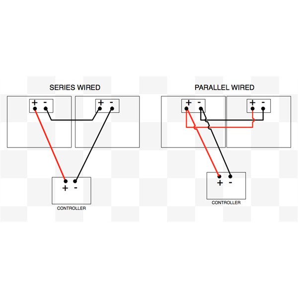
Solar Panel Wiring
FollowupID:
890979
Follow Up By: Deejay - Sunday, May 13, 2018 at 18:16
Sunday, May 13, 2018 at 18:16
Thanks Allan.
First question. Despite the information I was given in my posting of a few weeks back, does it really matter which way the panel is wired - series or parallel? What would YOU advise? If you reckon 'series' then I'll swap it back.
Second point. I have attempted to wire the panels in parallel, (only because the guy at Springers said that is how all other panels are wired) and looking at your sketch I may have c*cked up.
I took the red wire from each panel and the red wire of the lead going back to the car, twisted all 3 together and clamped them inside one of those 'cap' shaped things that have a pinching screw in the side. I did the same for the 3 black leads. Have I got this wrong?
FollowupID:
890980
Follow Up By: Allan B (Sunshine Coast) - Sunday, May 13, 2018 at 18:30
Sunday, May 13, 2018 at 18:30
.
Deejay,
There are merits for either series or parallel wiring, but given the specs of your panels, I would wire them in parallel.
Your description of wiring (all reds joined together etc.) is correct for parallel operation. Do your panels have terminals on the back or just red & black wires coming out from inside the panels?
It still may be a good idea to totally disconnect each panel and then test each one for open-circuit voltage and short circuit current as before. At such time you can observe if each red wire is truly positive..... the manufacturer could have got it wrong. You will not need strong sunlight to check the polarity.
FollowupID:
890981
Reply By: Member - Aussie Jeepster - Thursday, May 10, 2018 at 22:37
Reply By: Member - Aussie Jeepster - Thursday, May 10, 2018 at 22:41
Thursday, May 10, 2018 at 22:41
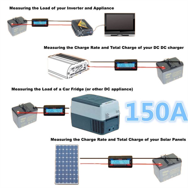
wiring up
I just found this which might help.
AnswerID:
618794
Reply By: Malcom M - Friday, May 11, 2018 at 06:22
Friday, May 11, 2018 at 06:22
You could simply plug the panels a 12v light bulb and see what current you get.
That'll tell you if the panels + regulator output is happy and rule them out.
If its bad then put the bulb directly on the panels...
AnswerID:
618796