Solar Panel blows globes. Battery doesn't
Submitted: Friday, Sep 25, 2020 at 21:23
ThreadID:
140546
Views:
9849
Replies:
6
FollowUps:
11
This Thread has been Archived
Member - Bill D
Hello all - this is a basic electronics question and I know a bit of basic electronics, but I can't work this one out. If I put a 55 watt car headlight globe across a car battery it lights up brightly. If I put the same 12 volt globe across a 12v solar panel, it blows as soon as the sun shines brightly. This is despite the fact that the battery could deliver several hundred cold cranking amps if needed, while the solar panel can only deliver about 8 amps. Why is this?
Bill D
Reply By: Member - Rod N (QLD) - Friday, Sep 25, 2020 at 21:34
Friday, Sep 25, 2020 at 21:34
Do you have a 12v regulator on the solar panel? Unregulated the panel voltage can be about 20v, too high for the bulb?
AnswerID:
633525
Follow Up By: Member - Bill D - Friday, Sep 25, 2020 at 21:44
Friday, Sep 25, 2020 at 21:44
Good point, Rod and thanks. It's not regulated, so I'll try it with a regulator if the sun ever comes out in
Adelaide again. VoC of that panel is a bit over 20v andI didn't know that just 8 extra volts could blow a globe.
Bill
FollowupID:
910573
Follow Up By: HKB Electronics - Saturday, Sep 26, 2020 at 10:14
Saturday, Sep 26, 2020 at 10:14
Some regulators won't work without a battery, others might but the battery smooths the output of the regulator, with it you may still get large voltage transients.
FollowupID:
910580
Reply By: Gary T7 - Friday, Sep 25, 2020 at 22:47
Friday, Sep 25, 2020 at 22:47
Volts are pressure, 12v to 20 volts is a lot, nearly double .Try blowing up a balloon to max then doubling the pressure. That's what you just did to the globe . Amps has no relevance here.
AnswerID:
633526
Reply By: RMD - Friday, Sep 25, 2020 at 23:11
Friday, Sep 25, 2020 at 23:11
Bill D
A globe only accepts the amount of current the globe can use while on 12v, therefore, 55w @12v will be drawing around/close to 4.5 amps depending on how hot the filament is actually running. Because the battery voltage doesn't rise the globe stays alive as designed to do. ie, the globe is a resistance and resists current flow to 4.5amp at a 12v "pressure"
A solar panel in good sun with an 8amp ability at around 18v , the 18v being 50%more voltage than the battery and globe combination means the globe will have around 80w being forced through it and a current of 7 to 8 amps instead of 4.5 amps. That will fry the globe, the same as an alternator will do if the regulator of the vehicle goes way too high in voltage. Someone mentioned a regulator, great idea, BUT, solar regulators are designed to have a battery on the wires and they regulate to that. The globe is then just a draw on the circuit. Just a solar panel to regulator to globe may not end
well as the regulator doesn't know what is what at it's output side.
Have a look at OHMS LAW as it is the basis for all electrical flows and wattage in circuits. BASICS- 1v will push 1 amp through 1 Ohm resistance.
AnswerID:
633527
Reply By: Nomadic Navara - Saturday, Sep 26, 2020 at 08:44
Saturday, Sep 26, 2020 at 08:44
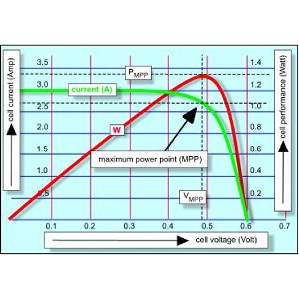
The graphic demonstrates the dynamics of a solar cell. The pannels that we commonly use for charging our 12 V batteries have 36 cells, so multiply the voltage on the bottom line by 36 to reflect how a full "12 V panel" works. A vehicle alternator works roughly the same way, people don't realise that as we rarely see an alternator without a working regulator on it. The curve for an alternator is different from the solar cell but the big difference is the capability of the two. An alternator is generally capable of supplying very much more power than we use in any item we power with it. The solar panels we use often are not capable of powering the total load we use of a night time if we switched it on during daylight hours.
Looking at the curve below you will see that when no current is being drawn from the cell its voltage is zero (the green line.) At that time the power is zero (the red line.) When we start to put small loads on the cell you will see the voltage starting to fall as the power starts to rise. As we increase the power we draw from the cell the voltage continues falling as the power increases. This continues until we reach the maximum power point (MPP.) If we continue increasing the load on the cell you will notice that the voltage commences dropping rapidly and the power curve drops away as the panel is not capable of delivering full power.
Solar Cell
When we mount panels on our vans we use controllers to ensure those panels do not overcharge the battery (or pop your incandescent globes.) The simple ones just regulate the current so that the system supplies a suitable charging voltage to the battery. In our case, the cell would be operating ar around the 0.4 V point (depending upon the exact absorption we choose to set in the regulator/controller.) You can read the value of current the cell supplies from the curve - in the ideal condition. However we can not achieve this as out panels are not pointing directly at the sun and also the cell performance drops off as they are heated up by the sun. These are called PWM (pulse width modulation) controllers. You will see from the red curve that when using these controllers we cannot achieve the maximum power that the panels manufacturers say their panels are capable of generating.
There are a second type of controller that manipulates the voltage and current relationships so that operate the panel at its MPP. These are called MPP controllers. They work
well in our household
grid connect systems and the panels can produce their maximum power potential. However, they do not provide much power gain in our caravan systems and in many cases they provide less power than PWM controllers.
AnswerID:
633529
Follow Up By: RMD - Saturday, Sep 26, 2020 at 09:17
Saturday, Sep 26, 2020 at 09:17
I think the MPPT controllers DO gather more power for a caravan/
camping system. My setup can have 9 amps current in the solar line and 11 amps actually going into the battery as charge. More than a 10% increase. If it was the share market, which way around would be best?
Line 1 in paragraph 2.
I know the solar panel has to start up in sunlight, but the voltage does increase when in light but perhaps no current. The voltage of the panel isn't reliant on current happening. If the voltage relied on current being drawn, how can you measure open circuit voltage of a panel if current not being drawn off. The graph is a relationship of load and voltage. The cell current doesn't suddenly start at 3 amps when voltage is miniscule, perhaps not the best graph for the OP.
FollowupID:
910578
Reply By: Member - shane r1 - Saturday, Sep 26, 2020 at 08:48
Saturday, Sep 26, 2020 at 08:48
Simply too much voltage!
AnswerID:
633530
Reply By: Member - Bill D - Saturday, Sep 26, 2020 at 11:13
Saturday, Sep 26, 2020 at 11:13
Thanks to all, especially Nomadic Navara and RMD for that detailed discussion. And to Shane and Gary for summarising it all, ie too many volts forcing too much current through the globe. A great example of how forums should work, with the detailed replies giving us all food for thought, and nobody slinging off at the silly old bloke who asked the question in the first place, ie me. Bill.
AnswerID:
633538
Follow Up By: qldcamper - Saturday, Sep 26, 2020 at 11:49
Saturday, Sep 26, 2020 at 11:49
No such thing as a silly question, but can the same be said for answers?
No reference to anything in this thread.
You wouldnt be attempting to make an electric version of a skylite by any chance?
FollowupID:
910590
Follow Up By: RMD - Saturday, Sep 26, 2020 at 12:02
Saturday, Sep 26, 2020 at 12:02
QLD, sounds a bit like it is for that reason. Good spotting.
I made a hot air heater which uses solar panel and electronics to switch on airflow via fan when temp is high enough. You need more than just a panel power source, as electronics require metering and regulation and curious things happen with ebay circuits which is found out later when items don't function or get spurious signals from regs which stuff up the controllers. Done that and when the solar diminishes it does funny things at a critical low power delivery point.
FollowupID:
910591
Follow Up By: Member - Bill D - Saturday, Sep 26, 2020 at 12:26
Saturday, Sep 26, 2020 at 12:26
Not a skylite. I was making a test load for solar panels using several switchable 55W globes in parallel. I was going to use a variable resistance, but it would need to be rated for up to 200 watts, so a bit expensive and I'm sure it would get hot. I've made the load tester now and scribbled a note on it to remind me to switch all the globes on before connecting a panel. Quite proud of the tester - see picture, but you'd think that someone who could make such a super-professional looking thing would have known about excessive voltage. A little knowledge is a dangerous thing.
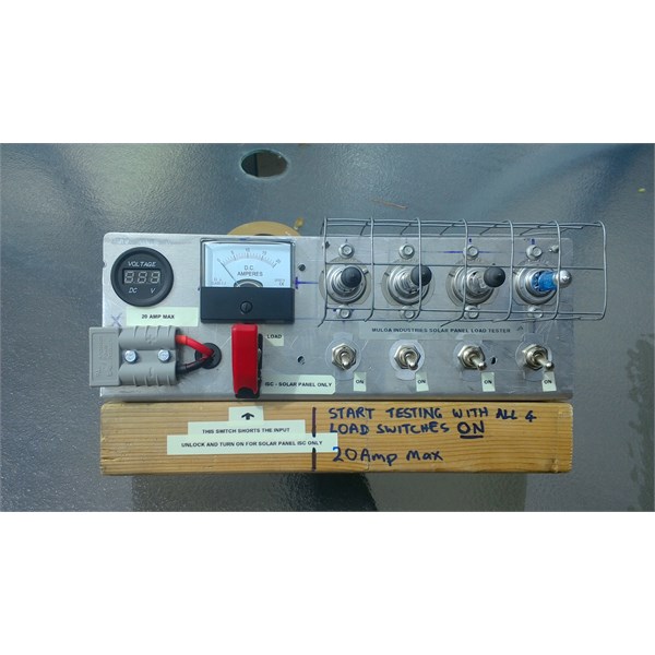
DIY Solar Panel Load Tester
FollowupID:
910592
Follow Up By: qldcamper - Saturday, Sep 26, 2020 at 12:33
Saturday, Sep 26, 2020 at 12:33
It is near impossible to find a solar regulator that works without a battery.
I used a philips 20 watt led oyster light that ran a bunch of series parallel leds at 120 Vdc, modified the board so they ran
well on 60V, removed the original 240Vac ballast and used a 7805 reg as a current regulator set at 300mA and supplied it with four 10 watt panels in series, works very
well from pretty early in the morning.
But it does dim quickly when a bird flys over.
Same principle wont work with a 55 watt 12V bulb, too much current to regulate.
FollowupID:
910593
Follow Up By: qldcamper - Saturday, Sep 26, 2020 at 12:53
Saturday, Sep 26, 2020 at 12:53
Sorry you snuck that in while I was writing.
If you used 24V bulbs and a single panel the bulbs wouldnt blow, but you would need twice as many to get the same current loading.
Go to an auto sparky that does road trucks, they throw away H4 bulbs that still have one element intact, ask nicely and Im sure they will hang on to some for you.
FollowupID:
910594
Follow Up By: Member - Bill D - Saturday, Sep 26, 2020 at 13:10
Saturday, Sep 26, 2020 at 13:10
A good tip, but after I blew a few I found an Australian Ebay supplier who sells cheapy H7s at 10 for $25, so I blew the budget. The seller is ozstockdirect.
FollowupID:
910595
Follow Up By: RMD - Saturday, Sep 26, 2020 at 13:36
Saturday, Sep 26, 2020 at 13:36
Bill D
You are bluffing, I think that unit is a missile launch device, going on the RED missile switch. and the multiple switches are just countdown switches. It is in a box so should be a good pie warmer in the off times. 4 x H4 globes generate a lot of heat. Fries reflectors so a pie will heat ok!
FollowupID:
910597
Follow Up By: Member - Bill D - Saturday, Sep 26, 2020 at 15:47
Saturday, Sep 26, 2020 at 15:47
My fiendish plan exposed. I was going to start WWIII and keep my quiche warm at the same time. Hang on, what was I thinking, real men don't eat quiche.
FollowupID:
910603