STECA solar regulator
Submitted: Sunday, Feb 08, 2015 at 08:34
ThreadID:
111038
Views:
4992
Replies:
3
FollowUps:
14
This Thread has been Archived
Roachie.kadina.sa.au
Just wondering if anybody has one of these Steca units on their 4x4 or van for charging aux batteries?
If so, do you also have a 240 volt battery charger hooked-up to the batteries for use to keep batteries charged up during the night and/or days with no sunshine?
My "new" Chev has a pair of solar panels on the roof, feeding through a Steca...something like this:
http://www.energymatters.com.au/steca-pr2020-20a-solar-charge-controller-p-2604.html?zenid=6bam7omfj7g1lr1j6h6ubhqkf7
However, for the life of me I cannot find any info on the interweb regarding the possibility of wiring-up a 240 volt charger to the batteries and leaving the Steca attached at the same time.
I'm "assuming" it would be okay, as the Steca does say it has all sorts of overload protection etc, so I'm guessing that if the 240v charger was attached and running, that the solar regulator would sense that the batteries were fully charged and stop sending current to the batteries.
Does this sound feasible to the gurus? Guessing and assuming are 2 words that have got me into deep trouble in the past and at the age of (almost) 60 I am starting to think it's better to ask a few dumb questions than to make an even dumber mistake!!! hahaha
Roachie
Reply By: The Original JohnR (Vic) - Sunday, Feb 08, 2015 at 09:17
Sunday, Feb 08, 2015 at 09:17
Hi Bill, have used one in our KK when we had it and it needs to be connected to the battery every time before the panels. The circuitry requires the battery to fire up, then when the panels are connected, it works
well.
I liked the one in the KK enough to have one on the solar system for the electric fence here. It is also a power controller, so if charging fails, it needn't actually wreck your battery, it will protect it.
I like the fact it has a LED read out to tell me the battery and charge capability. Great inexpensive little solar charger.
Oh, yes, leave it connected while the 240v charger is going
AnswerID:
545573
Reply By: Nomadic Navara - Sunday, Feb 08, 2015 at 09:29
Sunday, Feb 08, 2015 at 09:29
It does not matter what sort of controller you have you can connect another charger across it. It does not matter whether it's another solar charger, mains powered one or a DC-DC charger. The only thing you have to watch is that when they are all likely to operate together you are not supplying too much charge current to the battery.
When you have several chargers connected to a battery they will all have slightly different absorption set voltages. Whilst the battery is
well discharged all the chargers will supply a charge current up to their maximum capacity. As the battery terminal voltage rises to nearly the absorption voltage setting the battery will start to reduce the amount of current that it will accept. The output current of the chargers will reduce as a consequence. The charger with the highest voltage set point will supply the majority of the current. The ones with the lower voltage set points will cease supplying lots of current and will go into their float charge stage. When the charger with the highest voltage completes the absorption charging, it will then switch to float voltage. Nothing will be damaged during this progress. If you don't understand the terms I used then
go to this link.
The biggest problem you will have with your Steca controller is that it was designed for the communications industry and they use positive earth systems. This means that the positive terminals on the controller are all connected together and the negative terminals all work independently. If your battery is also charged from the vehicle alternator then the negative terminal of the battery will be earthed. You will be able to connect your mains powered battery charger across it. For the controller to work properly you will not be able to earth the negative sides of the solar panel connection lead or the load system. If you have something that you are powering from your battery that is metallic and the case is connected to the negative line (like a car radio) then make sure that it does not touch the metallic parts of your vehicle. If this happens you will short out the output current metering of the controller and this will effect your SOC readings.
AnswerID:
545574
Follow Up By: Roachie.kadina.sa.au - Sunday, Feb 08, 2015 at 16:31
Sunday, Feb 08, 2015 at 16:31
Thanks Peter....you've put my mind at ease.
I already have a 15 amp 3 stage smart charger in the cruiser, which I will move over to the "new" Chev.
Roachie
FollowupID:
833193
Follow Up By: The Original JohnR (Vic) - Sunday, Feb 08, 2015 at 19:02
Sunday, Feb 08, 2015 at 19:02
Peter, interested in your point about the negative earth and what you can't do. It worked perfectly in the KK using the earthed connection throughout. I don't have it now, but have the solar powered fence energiser .......
FollowupID:
833206
Follow Up By: The Original JohnR (Vic) - Sunday, Feb 08, 2015 at 19:03
Sunday, Feb 08, 2015 at 19:03
Positive earth that should have been
FollowupID:
833207
Follow Up By: Nomadic Navara - Sunday, Feb 08, 2015 at 23:20
Sunday, Feb 08, 2015 at 23:20
Any DC system can be designed with the positive or the negative leads as the active or switched leads. If the negative leads are the active leads then the positive side of the power sources or loads are connected to a common rail which is often the chassis in vehicles. This is referred to as a positive earth system. Most of the British vehicles with Lucas generators (dynamos, not alternators) had positive earth systems. The Telstra (and other telephone operator) systems are positive earth systems, They were designed this way as the early designers found there was less electrolysis problems with positive earth systems.
Steca and the early Plasmatronics regulators were designed to work in the communications industries installations and so are positive earth systems. The positive terminals are all strapped together (in fact in some Plasmatronics regulators there is only one positive terminal.) The negative terminals must be free to operate independently. If you wire the solar panel or the load terminal to the battery terminal (by earthing them) then you will stuff up the solar or output metering. If you connect the solar negative to the battery negative you will bypass the regulation stages in the regulator and the solar charging will run flat out without any regulation. Connecting the load and battery negatives together is less disastrous, you just loose the output metering and thus your State of charge (SOC) metering.
The above description is how a simple installation works. In a simple installation you must choose which one of the negative terminals you wish to earth. However there are work around fiddles where you can use external shunts to replace the internal load metering shunts and you are thus able to earth the negative side of the loads. (I was not prepared to go into the extra detail of how it is done until you questioned it.) The KK mob are rather more switched on than most other manufacturers when it came to 12 V systems. They may have gone into the extra expense and complication to provide these work-arounds.
These diagrams show how Plasmatronics do their regulators to extend there functionality.
FollowupID:
833217
Follow Up By: The Original JohnR (Vic) - Monday, Feb 09, 2015 at 08:37
Monday, Feb 09, 2015 at 08:37
Peter, I understand what you are saying about the basis of negative earth systems and the common rail of the chassis.
It wasn't the KK mob who fitted up the Steca, I always thought their exchange rate challenged me. K$ versus Au$. ;-) A long way to the factory too
With the Steca 2020 there are three pairs of terminals. I never checked to see whether there was a common positive or negative
FollowupID:
833223
Follow Up By: Nomadic Navara - Monday, Feb 09, 2015 at 09:15
Monday, Feb 09, 2015 at 09:15
John, most dabblers in solar systems seem to miss the point of positive grounding and many of them wonder why their regulators do not work properly. Most of the regulators that look like clones of the Plasmatronic and Steca units are positive earth devices. Steca have a good diagram (for trained technicians) in their handbook that may be overlooked by amateurs. There are many examples where even licensed electricians have overlooked the issue.
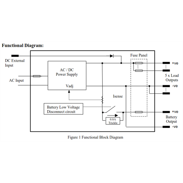
Steca Grounding
The above is taken from page 6 of one of their handbooks.
For anyone contemplating one of these types of regulators with the internal SOC metering I would suggest that you gravitate towards the Plasmatronics
Dingo 20 A regulator. There are far fewer pitfalls when installing them.
FollowupID:
833224
Follow Up By: Nomadic Navara - Monday, Feb 09, 2015 at 09:20
Monday, Feb 09, 2015 at 09:20
Well that was a stuff up, serves me right for not previewing my message. This is what should have appeared in the previous FollowUp.
Steca Grounding
FollowupID:
833225
Follow Up By: Rod - Friday, Feb 13, 2015 at 16:31
Friday, Feb 13, 2015 at 16:31
I accidentally wrecked two Stecca controllers until I worked out they were positively earthed. The manual that came with them was an awkward translation from german to english, but to be fair, the supplied circuit diagrams were clear.
I had commoned the negative of the battery, controller and panels together. If you do not do this, they are a great unit. My fault, but beware.
FollowupID:
833523
Follow Up By: Roachie.kadina.sa.au - Friday, Feb 13, 2015 at 17:00
Friday, Feb 13, 2015 at 17:00
Thanks Peter and Rod,
The Steca is already wired-up in the canopy of the Chev, as per the 2nd diagram that peter posted....although there is nothing connected to the right hand "LOAD" outputs. If I do decide to connect a light to those, I will be sure to keep the wiring independent of the battery connections (as per the diagram).
Not sure when/why I would wish to use that LOAD circuit, but one possibility could be an internal canopy light that stays on for a couple of hours between dusk and bedtime.....makes it easier to find the fridge! hahaha
Roachie
FollowupID:
833525
Follow Up By: The Original JohnR (Vic) - Saturday, Feb 14, 2015 at 15:20
Saturday, Feb 14, 2015 at 15:20
Roachie, the other connection point protects the battery from too deep a discharge. If you left your lights on accidentally or the fridge didn't have the low voltage disconnect, it is useful for that. It has protected the battery on my electric fence quite nicely
FollowupID:
833577
Follow Up By: Roachie.kadina.sa.au - Saturday, Feb 14, 2015 at 18:23
Saturday, Feb 14, 2015 at 18:23
John,
I don't understand what you're saying.....
When you say: "the other connection point protects the battery.......etc", are you referring to the "LOAD" output circuit?
If so, then I don't understand how having something connected as a load would protect the battery/ies if the fridge (or other item/s) kept drawing on them to a point where they were too deeply discharged.
Or have I got the bull by the foot? (Wouldn't be the first time!!!...hahaha).
Roachie
FollowupID:
833591
Follow Up By: Nomadic Navara - Saturday, Feb 14, 2015 at 18:55
Saturday, Feb 14, 2015 at 18:55
Roachie, in your case with the load connected directly to the battery and external shunt/s used to meter the load currents you do not have any low voltage connection via the load terminals. However if you have a simple basic installation with the load being connected to the load terminals then the Steca internal circuitry will provide low voltage protection. I think John may be a little confused regarding your installation.
FollowupID:
833593
Reply By: Bob Y. - Qld - Sunday, Feb 08, 2015 at 13:25
Sunday, Feb 08, 2015 at 13:25
Roachie,
When I was setting up our slide-on camper, I procrastinated long and hard about what solar/240v charger system to fit. Wanted MPPT solar, 240v charger(Ctek 25 amp), LED battery monitor and smart charger off the alternator. When you add the cost of these, using quality items, they add up to almost the same cost as a Redarc BMS system. Bit pricey, but got one cheaper from Kulkynne Kampers, at just over a grand. Charging rate is a bit light at only 15 amps max, but a new model(with a new price!) is rated at 30 amps max.
We haven't done a great deal with the camper, in remote areas, but it all works
well. Have a 160w panel mounted on the roof, and plan to add a couple more panels, when/if, we ever get away on our bucket trip. The fact that Mick O had the same unit, and he had desert tested it was a bit of a carrot for me too.
The third thing that helped me decide was the fact that the BMS doesn't need an "ign" sensing wire run into the unit, to switch between alternator or solar charging. The BMS meets the KISS principles. :-)
Bob
AnswerID:
545583
Follow Up By: oldtrack123 - Sunday, Feb 08, 2015 at 15:25
Sunday, Feb 08, 2015 at 15:25
Hi Bob
But you still do not have a 240V charger
The OP's question, whch has been
well answered by PeterD
PeterQ
FollowupID:
833187
Follow Up By: Bob Y. - Qld - Sunday, Feb 08, 2015 at 16:34
Sunday, Feb 08, 2015 at 16:34
Peter,
The BMS has a built in 240v 15 amp charger.
Yes, Peter's informative post might be all the info Roachie needs, but as it was indicated that the Steca is positive earth, I can see future dramas in a negative earth vehicle, used off road. Just giving an alternative........
Bob
FollowupID:
833194