Engel Fridge help sought
Submitted: Tuesday, Jul 20, 2021 at 11:35
ThreadID:
142228
Views:
11039
Replies:
9
FollowUps:
10
This Thread has been Archived
Member - William B (The Shire)
Hello.
I need some info from more knowledgeable people than me regarding a 14 L Engel fridge/freezer.
I acquired a non working fridge to play with, when I got it the fan worked and that was all.
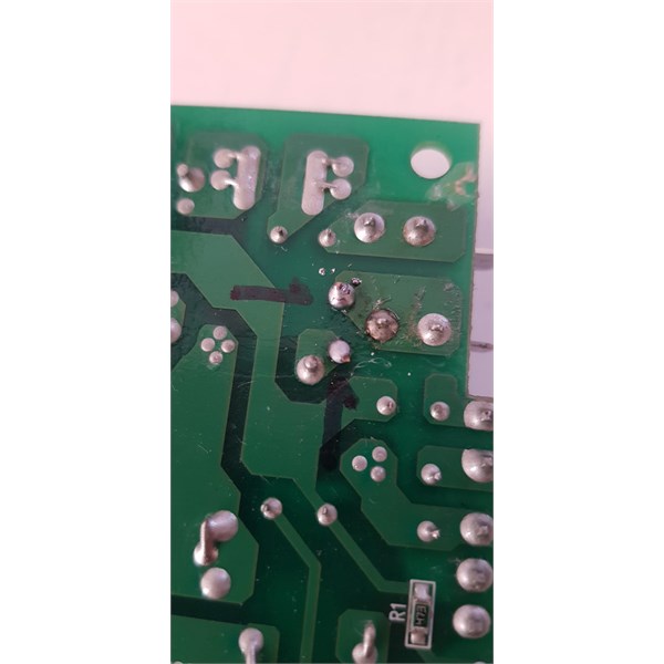
I pulled it apart and found a component that was "blown" photo included, with my limited knowledge to me it looks like some form of fuse. There are similar components nearby.
If I bridge the two ends together the compressor kicks in.
I tried a google search but came up with nothing that was useful, can any one identify the component so I can try to track one down.
Thank you in advance.
William
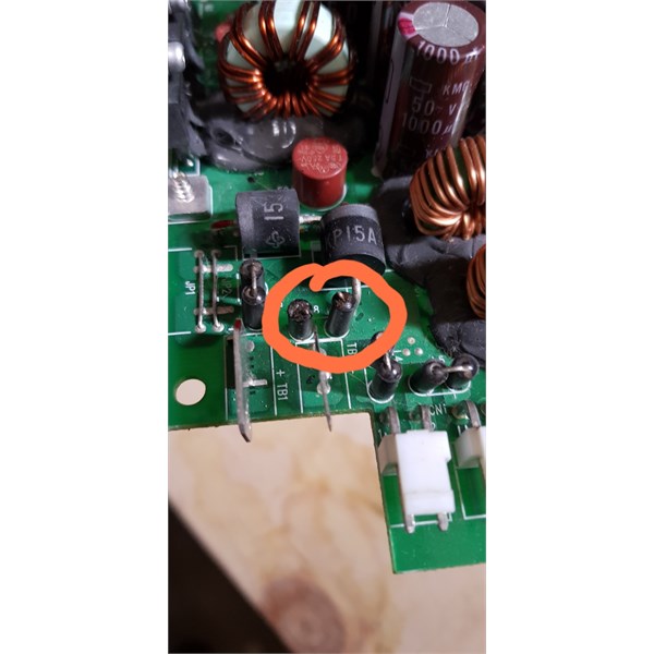
Blown component
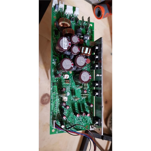
Board
Reply By: Member - Jim S1 - Tuesday, Jul 20, 2021 at 12:05
Tuesday, Jul 20, 2021 at 12:05
I’d start by taking it to Jaycar and see if they can help.
Cheers
Jim
AnswerID:
637223
Follow Up By: Member - William B (The Shire) - Tuesday, Jul 20, 2021 at 12:10
Tuesday, Jul 20, 2021 at 12:10
Hi Jim S1,
Currently with the
Sydney lock down that is not a option, hopefully if I can identify the item I can online
shop or click and collect.
William
FollowupID:
915230
Reply By: Kazza055 - Tuesday, Jul 20, 2021 at 12:22
Tuesday, Jul 20, 2021 at 12:22
I would remove one of the other one and test it with a multi meter.
Is there any label on the PCB that might identify its function.
There are a scattering of circuit diagrams out there but you might not find the same one but still might be able to look around that part of the circuit to give you more info.
I don't recall seeing a component like that in all my electronic life so I doubt Jaycar will know but you never know.
AnswerID:
637224
Reply By: kgarn - Tuesday, Jul 20, 2021 at 13:36
Tuesday, Jul 20, 2021 at 13:36
I think they may be a couple of ferrite beads ( L7, L8)
jaycar ferrites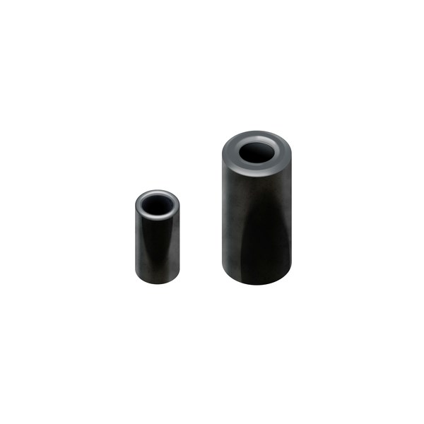
Ferrite
AnswerID:
637225
Reply By: ExplorOz - David & Michelle - Tuesday, Jul 20, 2021 at 13:42
Tuesday, Jul 20, 2021 at 13:42
The designation for L on a PCB is generally "Coil, Inductor, Bead, Ferrite Bead". To me it looks like an RF inductor wound ferrite bead. When you say you shorted it and it works are you referring to bridging across the top of the two coil looking bits?
De solder it and have a look from the bottom I think you will find a wire enters it (maybe has some loops internally) then passes out to the next one.
David
AnswerID:
637226
Follow Up By: Member - William B (The Shire) - Tuesday, Jul 20, 2021 at 14:42
Tuesday, Jul 20, 2021 at 14:42
Thanks for your reply David,
I put a small wire across the top of the 2 black upright cylinders and the compressor kicked in.
Excuse my ignorance but are they 2 single ferrites joined ( or not in this instance ) together at the top (bridged) or a single unit.
Most "RF inductor wound ferrite bead" I see on google are single units.
I will try your suggestion of de soldering them and see if I can gain any more info.
William
FollowupID:
915234
Reply By: RMD - Tuesday, Jul 20, 2021 at 13:46
Tuesday, Jul 20, 2021 at 13:46
William
Good on you for having a go and disassembling the power pack. They aren't easy to get apart.
I have been playing around with an MT45 which became defunct as many of them do. On my board, (looks the same) those 4 similar units are simply a wire through a two ferrite beads on each one. That one in particular feed the negative line to the CATHODE of the RH side 15A ZENER diode in the circle background. I would simply solder a piece of fuse wire, 10amp perhaps across the ferrite tops or replace the item with a fusible device of some nature.
The brownish red device above the large black 15A ZENER diodes is a fuse of 5 Amp. there should be two of those , one is hidden in amongst the Electrolytic capacitors.
My guess is, someone reversed polarity on the feed line and the large ZENERs passed enough current to blow the top off the link. It would melt to save the MosFETS on the heat sink.
Let us know if it goes again. Those boards are very expensive. There must be quite a few Engels around which have minor electronic faults but don't run.
EDIT, Anode changed to cathode, made a mistake, I had my electrons Frack to Bunt.
AnswerID:
637227
Reply By: Allan B (Sunshine Coast) - Tuesday, Jul 20, 2021 at 15:01
Tuesday, Jul 20, 2021 at 15:01
.William,
The device you circled is indeed a pair of ferrite beads, cylindrical form. They are arranged as a pair of ferrites with a conductor rising through one then looping back to the circuit board through the other. I can see four such sets in your photo. Their purpose is to eliminate high frequency electrical 'noise' in the circuit.
The one that has "blown" is simply the wire link that passes through the ferrites and would be the result of excessive current. The cause of this excessive current can only be guessed at but may be because of a failed electronic component although it must have been pretty significant to fuse the link of substantial current carrying capacity. It could also have been caused by some conductor coming into contact with the link.
You say that the compressor runs when the blown link is bridged so that is a hopeful
sign. You could try replacing the blown link with a piece of suitable copper wire by re-soldering on the underside of the board. Wire size is not critical and you could gauge from the intact nearby links. However I would not guarantee success considering the excessive current that must have passed in the circuit but I do wish you good luck.
AnswerID:
637230
Follow Up By: RMD - Tuesday, Jul 20, 2021 at 16:15
Tuesday, Jul 20, 2021 at 16:15
Allan.
That link which has fused carries all the 12v _ve to the board and if polarity has been reversed, the link on the LHS of it is the return path of current passing through the two diodes which would be biased ON. and very shorted to the lhs link and the +ve terminal. The LHS link hasn't burned though. Both links and diodes immediately beyond the spade terminals are involved.
The picture shows the spade blades. Left on is +ve, Right one is -ve, 12v feeds.
FollowupID:
915236
Follow Up By: Allan B (Sunshine Coast) - Tuesday, Jul 20, 2021 at 16:36
Tuesday, Jul 20, 2021 at 16:36
.
RMD, yes thank you, very informative. Although I don't know what William will make of it?
FollowupID:
915237
Follow Up By: Member - William B (The Shire) - Tuesday, Jul 20, 2021 at 19:27
Tuesday, Jul 20, 2021 at 19:27
Thank you Allan,
If I follow what has been said I should be able to de solder the 2 ends where the wires loop from the main board and re solder with whatever size wire will fit through the ferriles. I think that might be easier with my soldering kit and abilities than soldering across the two ferriles.
I understand (a little bit) what RMD has written
William
FollowupID:
915242
Follow Up By: Allan B (Sunshine Coast) - Tuesday, Jul 20, 2021 at 20:06
Tuesday, Jul 20, 2021 at 20:06
.
William, yes that's right. The replacement wire should be no smaller than the wire it replaces and the holes in the board dictate the maximum wire size unless you need to drill them out a little. Being larger than the original does not affect the electrical operation.
When de-soldering the existing wire stumps, melt the solder and pull the stumps out from the component side so as to avoid lifting the copper tracks off the board. If the hole remains full of solder you could drill it out with an appropriately sized drill.
I did not mean that you would not understand RMD's expression, only that it had little significance to your situation and could confuse.
FollowupID:
915243
Follow Up By: RMD - Tuesday, Jul 20, 2021 at 22:04
Tuesday, Jul 20, 2021 at 22:04
Allan.
If William is capable of dismantling the power supply to that degree, he has some ability and underrates himself a little. From my, I thought, clear instructions, a yr 9 student in school tech class could follow the Negative spade,( it is marked so) and then follow those large diode direction and their connections directly to the Positive spade terminal, it will be obvious the reversal of applied current would cause that failure/burnt off link. Hopefully no other damage has occurred. It will mean little if you haven't got the circuit board in front of you. There are ferrites on the legs of some other components too.
I think what I mentioned and described has "everything" to do with the fault he has described. Strange you cannot see that.
FollowupID:
915245
Follow Up By: Allan B (Sunshine Coast) - Tuesday, Jul 20, 2021 at 22:25
Tuesday, Jul 20, 2021 at 22:25
.
Strange indeed!
FollowupID:
915246
Reply By: RMD - Wednesday, Jul 21, 2021 at 10:41
Wednesday, Jul 21, 2021 at 10:41
William
If the fridge has a ciggy plug end on the cable, ie, the one which is
grey and has a fluted body, check to make sure it hasn't been unscrewed and the pins placed back into the body the wrong way, ie WRONG POLARITY supplied to fridge cable. I have one of those type and see it as a problem IF ever taken apart. If it is wrong then it explains the link fused/melted in the fridge.
AnswerID:
637244
Reply By: Life Member - Woodsy - Wednesday, Jul 21, 2021 at 12:02
Wednesday, Jul 21, 2021 at 12:02
Hi guys!
I read this thread with interest and thought to myself "Now this is what our site is all about, help with no slanging matches"
Well done everyone!
AnswerID:
637248
Reply By: Member - William B (The Shire) - Wednesday, Jul 21, 2021 at 13:46
Wednesday, Jul 21, 2021 at 13:46
Hello again,
Thank you every one for all the valuable information.
I have repaired the circuit board with help from the contributors on this site.
Currently the fridge is working
well, currently sitting on -15.
I am very happy, for a little bit of time, some scrap wire and with my dodgy soldering skills this fridge is working, I'll leave it run for a while.
I don't think I will use it as my main fridge as I have 1 other and my faithful Bushman.
Photos attached of my repair, it is pretty good considering my soldering iron and lack of skill.
William
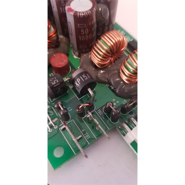
Repair
Solder joint
AnswerID:
637252
Follow Up By: RMD - Wednesday, Jul 21, 2021 at 15:54
Wednesday, Jul 21, 2021 at 15:54
William
Ya done Bonza mate! Nothing wrong with the soldering. Good it is all working. Wish my one was relatively easy to find the cause.
FollowupID:
915258
Follow Up By: Allan B (Sunshine Coast) - Wednesday, Jul 21, 2021 at 16:47
Wednesday, Jul 21, 2021 at 16:47
.
Looks even better than the originals!
You're ready to fix the TV. lol
FollowupID:
915259