Sunday, May 18, 2025 at 10:55
Hi everyone,
Thanks so much for all your feedback and technical insights — it's been incredibly valuable throughout my setup planning process.
I've taken your advice seriously and made key improvements to the diagram and design. Here's what's changed and finalized:
Final Improvements Based on
Forum Suggestions
Wire Gauges and Fuse Ratings:
2 AWG is used for the short inverter run, and all 8 AWG circuits are now correctly fused with ANL or inline fuses (40A–80A). All key lines have fuses near battery terminals.
DC-DC Charging Paths:
The main 40A DC-DC charger handles alternator + solar charging for the under-bonnet AGM, while a separate 20A DC-DC charger takes care of the rear battery (avoids direct parallel setup). Ensures each battery receives proper staged charging.
Grounding Scheme Enhanced:
Added a dedicated body earth for each segment, and based on feedback, I may run a redundant earth cable from the alternator case to the AUX battery to eliminate potential grounding voltage drops.
Anderson Outputs and Load Splits:
A 2-w
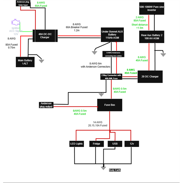
Updated Battery diagram
rear 20A charger and main fuse box (USB, fridge, LEDs). Fridge and other loads run on individual fused 14 AWG circuits from a proper fuse box.
Realistic Load Limits:
I’ve labeled the inverter as "500–1000W" to reflect real-world usage. I acknowledge that AGM isn't ideal for heavy or long inverter draw (like 2000W), so I’ll be mindful of usage patterns.
Component Simplification:
Replaced a bulky distribution block with a fused double Anderson plug which greatly simplified wiring while maintaining safety and flexibility.
Big Thanks to the ExplorOz Community
Special thanks to qldcamper, AllanB, Bigfish, Nick, Macca, and others for your honest feedback, technical checks, and experience-based suggestions. Your thoughts helped me identify real-world risks (especially regarding AGMs under-bonnet and inverter sizing).
I’ve learned heaps through this — not just about wiring, but about safety, redundancy, and what “good design” really means when you're off-
grid.
Here’s to safe
camping and cold fridges ??
– Dilan W (2012 Prado KDJ150R build)
AnswerID:
647942
Follow Up By: qldcamper - Sunday, May 18, 2025 at 11:58
Sunday, May 18, 2025 at 11:58
Thanks for your feedback, not many bother.
Just a
point of interest, if you don't already have the hardware your battery in the back could be lithium seeing it is on its own charging system and it could also have solar input into its dcdc charger. The cost difference for say a 70ah lifepo4 and 100 ah AGM would be minimal and weight and performance advantages
well worth considering.
One last thing I would suggest is a means to feed power from the rear battery to the front circuit in the event the front battery fails or just runs flat until you have the means to charge or replace it, just to keep the fridge going.
Good luck and safe travels.
FollowupID:
929064
Follow Up By: Allan B (Sunshine Coast) - Sunday, May 18, 2025 at 12:12
Sunday, May 18, 2025 at 12:12
.
Dilan, it still is not making much sense. Your system would work better and cost less if you put both batteries in parallel (or a single 200Ah lithium battery) in the rear of the vehicle with a single 40A dc-dc charger at the battery and supply both the inverter and all other accessories from that battery bank.
Apart from a simpler and more effective system you avoid putting an AGM battery in the hot engine bay.
It makes no sense to have one dc-dc charger obtaining its supply through another charger. I have never seen this done and cannot imagine why one would do so.
FollowupID:
929065
Follow Up By: Allan B (Sunshine Coast) - Sunday, May 18, 2025 at 13:31
Sunday, May 18, 2025 at 13:31
.
Dilan, another point about your inverter draw from a 100Ah AGM battery.
Firstly, it is recommended to not regularly discharge AGM batteries below 50% of their rated capacity, so your usable capacity is only 50Ah. So you might expect to run the inverter for about 30 minutes. But not so, because….
Secondly, these capacity (Ah) ratings only apply when the load is low, typically like 5 or 10 amps over a period of 10 hours. The nature of AGM batteries is that the faster you discharge (more amps) then the efficiency falls and you get less Ah than you would expect. It's called Peukert's law.
The reality is that your 100Ah AGM battery will only be able to support your inverter for about 5 to 10 minutes when running at 500-1000W before the battery is exhausted. Furthermore, the lifetime of the battery will be severely reduced when operated at these high discharge rates.
You will likely be very disappointed if you proceed with your current plan.
On the other hand, lithium batteries can be discharged down to 20% or even 10% of their capacity so you can get as much as 90Ah from a rated 100Ah lithium battery. Furthermore, lithium can deliver at high current without loss of efficiency so you can obtain this 90Ah in full. This then would support your inverter for maybe 50-60 minutes.
So a single 100Ah lithium battery in the rear could effectively provide your needs. Your pair of AGM's will fail miserably. Think about it.
FollowupID:
929066
Follow Up By: Member - McLaren3030 - Monday, May 19, 2025 at 08:10
Monday, May 19, 2025 at 08:10
Hi Dillon,
Thanks for your comments regarding feedback. Your diagram still shows that you are charging the cranking battery via the DC/DC charger and not directly from the alternator, is this still correct?
Secondly, further to Allan’s comment regarding LiFePo4 vs AGM, in the back of my wagon, I replaced 120 AmpHr AGM with a 175 AmpHr LiFePo4 after I had installed a 2,000 Watt inverter. The Inverter is used to run a Coffee Pod machine that pulls 1,300 Watts. The inverter would trip out when the Coffee Pod machine was started. The replacement 175 AmpHr LiFePo4 battery has a continuous discharge rating of 250 amps, and runs the Coffee Pod machine with ease along with the 60 Ltr. Engel Fridge that is also connected directly to the battery (not via the inverter). The battery is a PowerPaul Australia 175 Amp Cub battery.
Macca.
FollowupID:
929070
Follow Up By: qldcamper - Monday, May 19, 2025 at 08:20
Monday, May 19, 2025 at 08:20
Macca,
Maybe those cables are supplying the DCDC unit as the wire from the engine symbol is labled ACC so is likley representing the IGN feed to the DCDC.
FollowupID:
929071
Follow Up By: Member - nick boab - Monday, May 19, 2025 at 08:21
Monday, May 19, 2025 at 08:21
Dilon .
I'm with Alan I don't see the sense in this design . Note : not that I'm qualified to make any auto electrical/ Engineering advice . The updated diagram is in my mind only cosmetic and not really addressing the design factors , aswell
BIGFISH brought up the that the diagram appears to show that the vehicles charging goes straight to the 1st DC charger and not the main battery ?? , If so , why ?
If it was me , I would be at least designing the system with correct size cable from the battery to the 2000 watt inverter , not relying on a fuse to limit the inverter to half it's capacity . I don't think anyone thinks that the 100 amp hour AGM is ever going to cut it ....
your most likely going to want to upgrade the battery in some way in the future &
I can't see any benefit in splitting the batteries system especially if you're not going to be using the inverter to any extent .
FollowupID:
929072
Follow Up By: qldcamper - Monday, May 19, 2025 at 08:56
Monday, May 19, 2025 at 08:56
Nick,
There are times to run 2 seperate systems, such as medical equipment running of a devoted battery but charging through two DCDC units in series is normally only employed to limit overall load on the alternator when a second temporary system such as in a camper trailer is added now and then, in this case two 20 amp units would be more logical.
Ultimately there is only one logical configuration that can have minor variations to suit personal needs and everyone here can see this but Dilan seems intent on giving his design a go.
FollowupID:
929074