Welding with batteries
Submitted: Saturday, Nov 10, 2012 at 15:53
ThreadID:
98951
Views:
4870
Replies:
10
FollowUps:
22
This Thread has been Archived
pop2jocem
Although I am not a welder/boilermaker by trade, just a dumb mechanic (retired), I have done a fair bit of welding in my day job and being a notorious "shed dweller" also at home.
I have seen a few videos of people welding with 2 or 3 car batteries and as I had just replaced the 2 cranking batteries in the Cruiser I had the 2 old ones sitting in the shed (along with a lot of other junk if you take any notice of my other half (;-)) )
Now these 2 were still working OK but as they were nearly 8 years old I replaced them just to be safe. I thought I might charge them up and give the 24v welding a go as I had never tried this. I was most pleasantly surprised at how good a job could be done using this method after a couple of practise shots.
The only issue I could see was as there was no obvious way to control the amps it appeared to be a bit fierce for good control of the weld.
My question is (yes there is a question in here somewhere...lol) has anyone found a simple way to control the amps? I tried using another welding rod between the job and the earth but as you can imagine I very soon had 2 welding jobs on the go. OMG!!!!!
Cheers
Pop
Reply By: Mick O - Saturday, Nov 10, 2012 at 16:11
Saturday, Nov 10, 2012 at 16:11
Pop,
I looked at this same issues some time back and apart from carrying a heavy rheostat, the best (or only solution) appeared to be using extra length of cable between the handpiece and the final battery connection to provide resistance. We used jumper cables joined end to end as required. Mind you the trade off is always heat and it can quickly slag out even jumper cables if you don’t watch it.
Bush Welding Post
I think practise goes a long way towards proficiency in the field. There was no comparison between my efforts (very little welding experience) and Jaydubs (LOTS of welding experience) on our bush repairs. Of course having tool like a "readywelder" makes a big difference as
well.
Using the ready welder in the PilbaraBush Welding on the Sandy Blight
Cheers Mick
AnswerID:
498283
Reply By: Hairy (NT) - Saturday, Nov 10, 2012 at 16:18
Saturday, Nov 10, 2012 at 16:18
Gday,
Try using a larger diameter rod. If your using a 2.5, try a 3.2.
AnswerID:
498285
Follow Up By: Mick O - Saturday, Nov 10, 2012 at 16:56
Saturday, Nov 10, 2012 at 16:56
Howdy Hairy,
Michael (Mossvale) provided this bit of advice on Rods to me a while back. Haven't had an opportunity to put them to the test as yet (thankfully).
"Excellent rods to use for hard to weld metals and dissimilar steels is a CIG Weld All rods. You can buy a handy man pack with 10 and 12 gauge rods in the pack. They are excellent to weld stainless and spring steel also hardened steels like gears etc. They are very easy to use and are easy to strike an arc and continue a clean bead with little experience. They add material to the part welded and have the ability to "build" the rod material easily compared to standard rods. They are available from most engineering supplies for about $35 for a pack of about 20 rods of the two sizes mentioned above..Worth carrying a pack."
FollowupID:
774255
Follow Up By: Hairy (NT) - Saturday, Nov 10, 2012 at 17:10
Saturday, Nov 10, 2012 at 17:10
Gday Mick,
Weldall's are great rods and
well worth carying. They do have a fairly brittle flux so its adviseable to wrap them individually to stop them chipping. Also WIA 12p are a great GP rod with excellent down hand properties so its worth throwing in a few 12p's in different sizes too. Low Hydrogen are handy by most jobs where you would need them can be done with Weldalls.
Cheers
FollowupID:
774257
Reply By: Allan B (Member, SunCoast) - Saturday, Nov 10, 2012 at 16:54
Saturday, Nov 10, 2012 at 16:54
Apart from using longer cables from the batteries it can help to reduce the current if you attach the earth clamp to a point on the job remote from the weld site. The added resistance of the chassis or whatever will drop some current. Just be careful that the current will not be required to pass through lightweight sections that could overheat.
Inserting fence wire in the circuit has its own problems. A single strand will not be enough to carry any decent weld current so at least four strands in parallel will be needed, probably a metre or so long when paralleled. Keep it clear of flammable material and it will become
well and truly annealed in the process.
A steel tent pole can also be used and will dissipate the heat better due to the surface area, but it may not be real good as a tent pole afterwards!
AnswerID:
498289
Reply By: pop2jocem - Saturday, Nov 10, 2012 at 20:38
Saturday, Nov 10, 2012 at 20:38
Thanks for all that guys and for taking the time and effort to reply.
I sort of knew that somehow I would have to increase the resistance to cut the amps back
I tried welding rods of a larger size as in I was using 2.5's to do the welding and tried a couple of sizes bigger as the resistance but even that got a bit hot and bothered.
I know on the very old 3 phase welders that stood about 5' high they had a bank of resistors inside and a number of "chokes" if I remember the terminology correct that you pulled out or pushed in to control the amps. Obviously not practical to cart around. One idea I had and I don't know how practical, was to find a metal with a higher resistance to use as the resistor. Copper and aluminium are pretty good conductors so probably wouldn't provide enough resistance.
Mick
That Easy welder looks like a pretty niffty bit of kit. I guess it works with flux core MIG wire.
I presume it still uses a couple of batteries as a power source.
How does it go with getting a decent penetration and yes I am still talking about welding..(;-)))))
Cheers
Pop
AnswerID:
498302
Follow Up By: Michael ( Moss Vale NSW) - Saturday, Nov 10, 2012 at 21:39
Saturday, Nov 10, 2012 at 21:39
Pop! Another thing to try is to use the positive as the earth and use the negative with the rod. This tend to add material easier to the job and less splatter on AC welders, it could have the same effect on DC as
well . Worht a try.. Great to see it works ok with 2 batteries with a lot of years on them... regards Michael
FollowupID:
774270
Follow Up By: pop2jocem - Saturday, Nov 10, 2012 at 22:01
Saturday, Nov 10, 2012 at 22:01
Yeah you're right, tried both polarities and neg to rod seems o work best
Cheers
Pop
FollowupID:
774272
Follow Up By: Allan B (Member, SunCoast) - Saturday, Nov 10, 2012 at 22:08
Saturday, Nov 10, 2012 at 22:08
I believe negative to the electrode is standard for dc welding.
I do know that electron flow is from the negative (cathode) to the positive (anode) so I guess this must also apply to molecule movement through the plasma of the arc.
FollowupID:
774275
Follow Up By: Mick O - Sunday, Nov 11, 2012 at 09:28
Sunday, Nov 11, 2012 at 09:28
Pop,
you are correct on all assumptions. It does use a flux core wire. It also has facility to connect gas if you wish to carry a small bottle. Will work on a single battery but we've found 2 to be the best scenario. We've been very happy with the results and kit has provided good penetration on all our jobs so far. For the lighter jobs using thinner materials, it's a damn site easier to use and control than stick on 12V. We've welded up Rims, brackets, Scotties Trailer (the biggest job) and it has done a great job. On heavy steel, where you can get away without a lot of finesse, I'd go back to stick and throw in a third battery (if needed).
Cheers Mick
FollowupID:
774296
Follow Up By: pop2jocem - Sunday, Nov 11, 2012 at 11:09
Sunday, Nov 11, 2012 at 11:09
Mick,
Yeah cheers mate, I have a stick welder that I use for the heavier welding and a MIG for the thinner stuff as you do. I guess a gas shield would make a better looking job but the gasless works ok for me, I might have a look at one of those Easy welders. A bloke can never have too many toys...er I mean tools.
Safe travels
Pop
FollowupID:
774299
Follow Up By: pop2jocem - Sunday, Nov 11, 2012 at 12:02
Sunday, Nov 11, 2012 at 12:02
Note to self...Readywelder, readywelder, readywelder not Easywelder dumbo
FollowupID:
774305
Reply By: Eric Experience - Saturday, Nov 10, 2012 at 21:45
Saturday, Nov 10, 2012 at 21:45
Pop
You get a better start and a more stable arc if you have some inductance in the cct, the inductance is called a choke in weld speek. The inductance would be a bit heavy to carry around but you can improvise by winding your welding lead around a set of spanners, or some other bundle of steel rods ,tent pegs, etc Eric.
AnswerID:
498308
Follow Up By: Allan B (Member, SunCoast) - Saturday, Nov 10, 2012 at 22:02
Saturday, Nov 10, 2012 at 22:02
Hi Eric, Inductance will have no effect with dc welding current. Inductance only has effect in an alternating circuit. Fundamental of electrical physics I'm afraid.
Apart from reducing the supply voltage, you can only limit the dc current with circuit resistance.
FollowupID:
774273
Follow Up By: pop2jocem - Saturday, Nov 10, 2012 at 22:08
Saturday, Nov 10, 2012 at 22:08
Rickety rickety rats, I was thinking about wrapping the lead around a bit of pipe and giving it a shot....oh we'll
Cheers
Pop
FollowupID:
774274
Follow Up By: Allan B (Member, SunCoast) - Saturday, Nov 10, 2012 at 22:27
Saturday, Nov 10, 2012 at 22:27
In ac mains supplied welders, inductive chokes or heavy (usually cast iron) resistance is used to regulate the welding current. This also provides a characteristic of a slightly higher voltage to assist in arc initiation, with the voltage falling somewhat after the arc is established.
With mains supplied dc welders, any regulating inductors are located in the ac part of the circuit before rectification to dc takes place. There may also be some induction in the dc output to provide a degree of smoothing of the rectified current. This would be of no benefit in battery welding as the dc from the battery is already smooth, it has no ripple.
With rotary motor-driven dc welders, the welding current is provided from the driven generator and welding current control is achieved by the characteristic and controls of the generator.
FollowupID:
774277
Follow Up By: Michael ( Moss Vale NSW) - Saturday, Nov 10, 2012 at 22:41
Saturday, Nov 10, 2012 at 22:41
Allan, I think you are correct about the polarity with dc welding. It works
well on thin materials with ac also. I regularly used an old "bullet" DC welder in the seventies as an apprentice. Noisy thing from memory with a load on it. Michael
FollowupID:
774279
Follow Up By: pop2jocem - Saturday, Nov 10, 2012 at 22:41
Saturday, Nov 10, 2012 at 22:41
Hi Allan,
I have used both of the type of welders you have described without understanding any of the electrical engineering involved.
Now I am only very vaguely in touch with what is happening in either of the following examples so be gentle please.
As far as I can remember an electro magnet uses DC current to generate a magnetic field. I would imagine some current would be used/required in the generating of this field so would this have any effect in reducing or using up some of the amperage available??
The other example I had in mind is the old fashioned ignition coil where the collapsing of a field induced a much higher voltage in the secondary windings. And the longer I typed that the less sure I became how that might help in reducing the amperage in the primary windings. Just thinking that every time work was done power was consumed and some losses incurred.
All that probably sounds pretty naive so please consider.
Cheers
Pop
FollowupID:
774280
Follow Up By: Allan B (Member, SunCoast) - Saturday, Nov 10, 2012 at 23:00
Saturday, Nov 10, 2012 at 23:00
Michael, I do remember the "Bullet" welders you referred to. About 900mm long, 200mm diameter and probably painted
grey?
Maybe a Lincoln and looking like this?
Lincoln "Bullet" Welder
FollowupID:
774282
Follow Up By: Allan B (Member, SunCoast) - Saturday, Nov 10, 2012 at 23:20
Saturday, Nov 10, 2012 at 23:20
Pop, Actually, a steady dc current through an ideal coil uses no power to create the magnetic field. I know it sounds impossible but it is true. Where the power is consumed is that the coil will not be ideal, it will contain resistance of the copper wires and that will cause the losses that consume electrical power. This resistance accounts for some current limitation.
It is not the same for a coil passing alternating current. The ever changing (alternating) current produces a changing magnetic field which in turn causes a reverse EMF (voltage) to be created in the coil which opposes the original current and so limits the current flow.
With dc applied to a coil, at the instant of initial application the current is rising from zero to some steady value. During this short time the field strength is changing so the reverse EMF effect described above takes place briefly until the current reaches a maximum steady value.
The circumstance of an ignition coil is similar but in reverse. A steady maximum current and magnetic field is firstly established in the coil. when the points open and the current flow is interrupted, the magnetic field collapses and in so doing becomes a rapidly changing field which again induces the reverse EMF referred to above in the coil secondary winding. The results is a brief high voltage discharge. The condenser in the primary circuit serves to shunt, or short circuit, the primary winding at the moment of point opening and assist with rapid collapse of the magnetic field.
Fascinating stuff electricity, eh?
FollowupID:
774283
Follow Up By: Hairy (NT) - Sunday, Nov 11, 2012 at 05:05
Sunday, Nov 11, 2012 at 05:05
Makes sense to me Pop.....Sound is your best judge
FollowupID:
774289
Reply By: pop2jocem - Sunday, Nov 11, 2012 at 10:57
Sunday, Nov 11, 2012 at 10:57
Thanks guys for all your replies. I guess even if we didn't come up with a new "mousetrap" I for one have certainly learnt a bit more. As Allan said, electricity is fascinating stuff.
Oh
well, back to my other project trying to get a bit more output from a solar panel by figuring out how to rig up a heat sink to the back. Amazing how a photovoltaic cell that relies on the suns rays to produce power can be negatively affected by temperature rise.
Cheers
Pop
AnswerID:
498337
Follow Up By: Allan B (Member, SunCoast) - Sunday, Nov 11, 2012 at 11:18
Sunday, Nov 11, 2012 at 11:18
Pop, "negatively affected by temperature rise".
That is of course because the photovoltaic cell is energised by light (photons actually) whilst the sun's rays also contain the lower (infrared) frequencies that cause heat. But as you say, "Amazing".
I'm still contemplating a good current control method. It gives me something to think about when I am not steering the Troopy down a track!
FollowupID:
774300
Follow Up By: pop2jocem - Sunday, Nov 11, 2012 at 11:59
Sunday, Nov 11, 2012 at 11:59
Allan,
Surely I wouldn't be the first bloke to think about fitting some sort of infrared filter over the panel to allow the useful photons through and blocking the heat generating infrared or is this not possible?? I know prisms break white light into a visible spectrum because of the different wavelengths for different "colours' and I guess infrared is just a "colour' that is not visible to the naked eye.
As you are probably thinking by now "this bloke has way too much time on his hands" (;-)).
With the welding part I was wondering, if the only way to decrease amps is to increase resistance, how would a length of say 25mm x 3mm flat bar about 2m long and bent into a tight zig zag for storage go as the resistor?
Cheers
Pop
PS Yeah I was one of those annoying kids that took alarm clocks apart just to see what made them tick (no pun intended)
FollowupID:
774304
Follow Up By: Allan B (Member, SunCoast) - Sunday, Nov 11, 2012 at 12:48
Sunday, Nov 11, 2012 at 12:48
Yes Pop, The flat steel bar could be OK as a series resistor. The electrode cable could be clamped to any point along it to "tap" the required resistance. 25mm x 3mm x 1 or 2m sounds about right to me.
This bar resistance would be very similar to the cast iron resistors incorporated into welders of long ago before adjustable core induction chokes were developed.
ps. I was delving into cast-off electrical appliances from the age of five. Still doing it!
FollowupID:
774311
Reply By: Eric Experience - Sunday, Nov 11, 2012 at 11:58
Sunday, Nov 11, 2012 at 11:58
Pop and Allan.
When welding the arc strikes and then collapses at a very high frequency, the frequency is determined by the inductance in the welder and the leads, the fact that the supply is DC makes no difference because the arc frequency is so high compared to the mains frequency. If you have a radio receiver near the welder you can very easily hear the RF from the arc. The chokes on dc welders are always after the rectifier otherwise the diodes would be destroyed by the high RF voltage. Eric
AnswerID:
498339
Follow Up By: pop2jocem - Sunday, Nov 11, 2012 at 12:16
Sunday, Nov 11, 2012 at 12:16
Eric,
So this happens with a DC current as
well as AC? I can see how that would happen with AC because of the polarity switching but I was under the impression that DC being a "smooth" current flow this may not occur.
I am not questioning what you say, I am just trying to get my head around what is going on.
Cheers
Pop
FollowupID:
774308
Follow Up By: Eric Experience - Monday, Nov 12, 2012 at 21:17
Monday, Nov 12, 2012 at 21:17
Pop.
I will try to explain in more detail.
When you start the weld by touching the electrode on the job the voltage at that instant drops to near zero but the current rises to say 200 amps, this causes the end of the electrode to melt and a small blob of metal about 1 mm in diameter drips of the end of the electrode onto the job. When this happens the connection is broken and the current drops to zero, the voltage rises to more than the 24 volt supply. The reason the voltage rises higher is because of the magnetic field around the leads that was created by the high current collapses and in doing so induces a voltage in the leads that adds to the battery voltage. This high voltage ignites the arc and causes another small piece of metal to move onto the job. This happens at about 1 million times a second. When you add extra inductance,or a choke into the lead the build up of the magnetic field is much greater so the voltage of the arc is greater, when the field collapses, this gives you a more stable arc. Because this happens so fast the effect is the same if the supply is dc or ac changing polarity at 50 timesecond. Eric
FollowupID:
774391
Reply By: Member - gujimbo - Sunday, Nov 11, 2012 at 12:19
Sunday, Nov 11, 2012 at 12:19
One of our repairs we recently did on the Madigan Line (camp 19) on a rear spring of a Land Rover, held up all the way back to
Melbourne.Kit was a ReadyWelder from the US.
Regards Jim
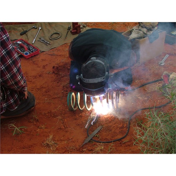
Spring Repair
AnswerID:
498342
Follow Up By: pop2jocem - Sunday, Nov 11, 2012 at 12:28
Sunday, Nov 11, 2012 at 12:28
You won me on the "usefullness" of a Readywelder. Just got to convince the minister of war and finance that one of these is far more use than the new carpets she wants...lol.
Cheers
Pop
FollowupID:
774310
Reply By: pop2jocem - Sunday, Nov 11, 2012 at 12:33
Sunday, Nov 11, 2012 at 12:33
Gents,
Going to be incommunicado for a bit...something about household jobs (boring)and a birthday party so I haven't lost interest, just the thumb and forefinger pressure on my ear lobe. Back later.
Cheers
Pop
AnswerID:
498345
Reply By: Peter_n_Margaret - Sunday, Nov 11, 2012 at 14:40
Sunday, Nov 11, 2012 at 14:40
Another vote for the "Readywelder 2".
Serious bit of kit. :-)
Weighs about 5kg. Paid $700 for mine in
Adelaide about 6 or 7 years ago.
Usually carry cored steel wire, but if we are towing the tinny then I also carry S/S and aluminium wire and gas.
Cheers,
Peter
OKA196 Motorhome
AnswerID:
498348