Help! I'm confused about charging ct batteries
Submitted: Tuesday, Jun 14, 2016 at 18:50
ThreadID:
132745
Views:
8100
Replies:
7
FollowUps:
18
This Thread has been Archived
Member - larsy
Hi all,
A quick brief of what I have.
I have 80 series, with dual batteries currently.
Main is crank only.
Aux, 120amp deep cycle, I run mainly fridge, and spotties (rarely).
From the aux battery is 8bs cable, it runs to the back of the car for the fridge, also Anderson plug at hitch.
------
Camper trailer has 100amp battery with 120watt solar. (This is usually enough but I would like to have other options in case)
Mainly run lights and small electronics. Not a lot.
-----
Ok question is,
Can I connect a cable of the tow hitch Anderson to charge the batteries in the camper trailer? Even though the fridge is running on Tis line.
Do I have to put a switch on the solar panel? (To disconnect it)
I have a photo below of what I'm thinking....
Anything I should be aware of?
I'm thinking as long as the Anderson from the car to the trailer is connected in parrallel it should be fine.
This is what I'm thinking
Reply By: Member - Roachie - Tuesday, Jun 14, 2016 at 19:34
Tuesday, Jun 14, 2016 at 19:34
That would be just about perfect I reckon!!
Good luck
AnswerID:
601323
Reply By: Member - John - Tuesday, Jun 14, 2016 at 20:02
Tuesday, Jun 14, 2016 at 20:02
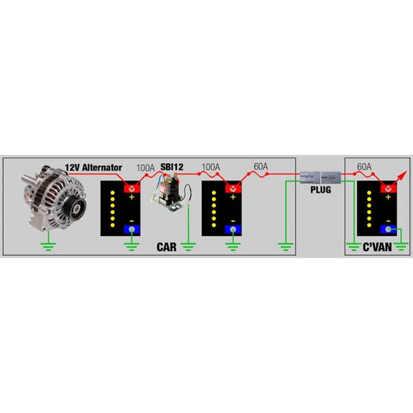
G'day, reckon you may need a DC-DC charger of some kind near your CT battery depending on how far the cable run and cable size is. DC-DC Charger should have a MPPT controller to maximize the charge from the solar panel. Like the diagram below, but changing the vehicle DC-DC Charger for the SBI 12.Cheers
AnswerID:
601324
Follow Up By: Frank P (NSW) - Tuesday, Jun 14, 2016 at 20:14
Tuesday, Jun 14, 2016 at 20:14
Based on my experience this is the way I would go as
well.
If the OP already has a solar reg, then a simpler non-solar DCDC charger may suffice.
Cheers
FollowupID:
870755
Follow Up By: Member - Boobook - Thursday, Jun 16, 2016 at 07:38
Thursday, Jun 16, 2016 at 07:38
A DC to DC charger really does not make sense under the bonnet to an aux battery. Compared to an isolator and good cable you can increase charge time for the Aus battery, and you lost the ability to double up batteries for winching and "Jump starting".
I even had tried a 40A DC to DC charger into my camper about 1 year a go on a trip. I have good thick cables in the car and camper and have a AH meter that I used to measure the charge. Guess what. The batteries took longer to charge, and the charge in AH was less over a 5 - 6 hour period ( about a days drive)
They fix a symptom and not the problem. The only reason you should consider them is if you cant remove and replace your thin cable out. They are a sub optimal fix and a last resort if you are ok with a non ideal setup.
FollowupID:
870831
Reply By: HKB Electronics - Tuesday, Jun 14, 2016 at 20:23
Tuesday, Jun 14, 2016 at 20:23
The 8B&S cable is to small to be trying to charge the trailer battery
off the car, you really need 6B&S at a minimum. I would also run directly from the VSR to the Anderson plug. I'm assuming the fridge is a compressor type.
AnswerID:
601326
Follow Up By: Member - larsy - Tuesday, Jun 14, 2016 at 20:47
Tuesday, Jun 14, 2016 at 20:47
Hi, thanks for the reply.
So if I run a seperate 6b&s cable from the vsr (aux battery) to the trailer via a Anderson this may supply enough voltage?
If I get enough voltage for charging, how would this conflict with my solar panel that charges my ct.
Can I also use one of ur fuse able links on ur website?
94 non turbo diesel lc.
Cheers
FollowupID:
870756
Follow Up By: HKB Electronics - Tuesday, Jun 14, 2016 at 21:59
Tuesday, Jun 14, 2016 at 21:59
I would install a new cable of at least 6B&S size preferably larger directly from the VSR aux connection via a suitable fuse to the Anderson plug. The trailer should also have at least 6B&S to the battery and a suitable fuse to protect the cable at that end.
You will only need to use one of my boosters if you have a low output type alternator.
Set it up that way and see how it performs, if you need to increase the voltage at the battery in the van you can always add a DCDC later.
You just need to wire the solar regulator up to the battery in the van, you can leave it connected the battery will then charge either via the car or the solar or both depending on what sources are available.
FollowupID:
870763
Reply By: Sand Man (SA) - Tuesday, Jun 14, 2016 at 23:01
Tuesday, Jun 14, 2016 at 23:01
Larsy,
I have a setup similar to your diagram but my auxiliary is in the back of my vehicle.
This auxiliary has a built-in isolator to protect the starter battery.
The cable from the starter terminates at an Anderson Connector in the back of the vehicle.
From this connector I have a Y cable connected. One circuit goes to the auxiliary battery.
A second circuit utilizes a patch lead that runs out the back of the tailgate to which I connect the camper cable. This circuit terminates at a Ctek D250S dc-dc charger in the camper and the output from this goes to a 200Ah battery bank. This ensures an optimum voltage exists at the camper end to maintain the batteries and I also have the ability to connect a solar panel to the solar port of the Ctek to provide a charging process when
free camping.
I have a battery monitor which displays the voltage level of the battery bank and can be switched to display the remaining Amp hour capacity.
My setup works extremely
well. I have 6 B&S cable from the primary battery to the rear Anderson connector, then 8 B&S cable to both the Auxiliary battery in the rear and to the camper connection. The Ctek provides a maximum draw of 20 amps and an 8 B&S cable run is adequate in this case.
All works extremely
well.
I would strongly recommend a dc-dc charger at the camper end of your charging circuit to overcome the voltage drop resulting from your long cable run.
AnswerID:
601328
Reply By: swampy - Wednesday, Jun 15, 2016 at 08:02
Wednesday, Jun 15, 2016 at 08:02
hi
Larsy
1/ In the engine bay there is typical large batt cable connecting
main batt to vsr to 1st aux ???
2/ In the diagram u have the written all the earths going to the chassis . It is more reliable to run an earth cable from all items back to the batteries . eg hard wire earths .
3/ solar panel connect straight to the battery or
fabricate a dedicated lead /plug of the battery to plug solar into [assuming regulator is panel mounted ]
4/ use a low volt disconnect to protect your 2x aux batteries from over discharge
around 12.00 volt is 50% capacity . They install between the battery pos and the load . Reasonably priced for low amp rated units .
You may need 1x for the car and 1x for the van .
swamp
AnswerID:
601330
Follow Up By: Bigfish - Wednesday, Jun 15, 2016 at 08:25
Wednesday, Jun 15, 2016 at 08:25
Think you will find around 12.0 volts is getting cloaser to 70-80% discharged.
FollowupID:
870772
Follow Up By: Member - larsy - Wednesday, Jun 15, 2016 at 10:50
Wednesday, Jun 15, 2016 at 10:50
This is similar too my install, the vsr was a.ready installed when I bought the car.
Wiring
I want to run a cable from the vsr to the batteries in the ct.
The solar pannel, connects to the ct battery via a mppt controller.
FollowupID:
870779
Follow Up By: Member - larsy - Wednesday, Jun 15, 2016 at 11:25
Wednesday, Jun 15, 2016 at 11:25
Just ran a test I had min 13.8 at rear Anderson with fridge running flat out.
FollowupID:
870781
Follow Up By: Frank P (NSW) - Wednesday, Jun 15, 2016 at 11:31
Wednesday, Jun 15, 2016 at 11:31
Larsy,
If it was
mine I'd take 6AWG cable from Pin 30 on the isolator or from the positive terminal on the start battery to the Anderson at the rear of the car and 6AWG from the trailer Anderson to a DC-DC charger in the CT. The charger should be placed as close as possible to the battery, with 8AWG leads from charger to the battery, positive fused. The positive input to the charger should also be fused near the charger.
The DC-DC charger, if it is a good one (Redarc and many others) and not a cheapie, will act as its own isolator and not pull down the start battery or backfeed from the CT to the car.
As Swampy says, if your solar reg is panel mounted, then connect it directly to the the CT battery via another Anderson or suitable connector. If your regulator is separate from the panels, mount it close to the battery with 6mm or 8AWG leads to the battery and then an Anderson for the solar panels.
If you haven't got a solar reg yet, you can get a DC-DC charger with solar input included, but they don't come cheap. Redarc BCDC 1225 or 1240 spring to mind and are popular and excellent products. You might need the low voltage version, depending on your vehicle's alternator and the voltage drop in the cable run.
IMO negative (6AWG) from the CT should come back through the Andersons to the Crank battery.
Cheers
FollowupID:
870782
Follow Up By: Frank P (NSW) - Wednesday, Jun 15, 2016 at 12:02
Wednesday, Jun 15, 2016 at 12:02
Larsy,
I just re-read your opening post.
You say you have 8bs (=8AWG) from leisure battery to fridge and Anderson.
You can use that setup (ie off the leisure battery +ve or pin 87 on the isolator) to power a DC-DC charger in your CT. But with 8AWG cable there will be a lot of wasted energy. Expect about a 1.5 volt drop in voltage at 25 amps, which is a typical load imposed by a 20 amp dc-dc charger. You would definitely need a low-voltage version dc-dc charger.
Without a dc-dc charger 8AWG won't work, IMO.
What sort of relay is it? Ie, amperage capacity. Is it like
one of these?
Cheers
FollowupID:
870785
Follow Up By: swampy - Wednesday, Jun 15, 2016 at 12:41
Wednesday, Jun 15, 2016 at 12:41
Hi
Bigfish
The volts you quoted are for a Flooded lead acid.
The volts for AGM batteries are as I quoted.
swamp
FollowupID:
870788
Follow Up By: swampy - Wednesday, Jun 15, 2016 at 12:49
Wednesday, Jun 15, 2016 at 12:49
hi Larsy
Do you have a standard auto relay as pictured or do u have a proper VSR ???
Is the cable in the engine bay at least as big as the factory batt cable??
It may sound obvious but u need to run a larger cables in the engine bay then from the aux batt via a fuse down to Anderson plug in 13mm2 cable .
swamp
FollowupID:
870789
Follow Up By: Member - larsy - Wednesday, Jun 15, 2016 at 14:23
Wednesday, Jun 15, 2016 at 14:23
Hi swamp, this the relay fitted when i bought the car.
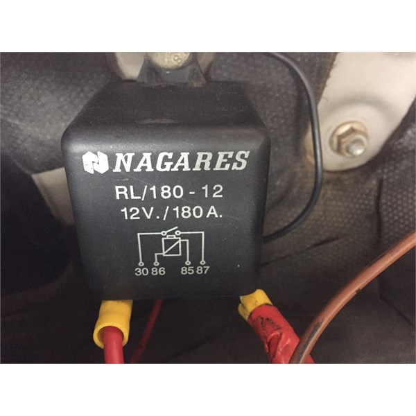
Relay.
From my research, when the ignition turns off it disconnects from the crank.
It keeps my second battery happily charges.
So I'm thinking of just getting a do to dc.
I had a fellow look at the cable run to the rear Anderson, he said its 6b&s.
The cable from the main to the Aux battery via the fuse is quite small??? Should I upgrade this?
Ready to rip it out lol, I have a week and I'm on the road though.
Cheers
FollowupID:
870798
Follow Up By: swampy - Wednesday, Jun 15, 2016 at 15:21
Wednesday, Jun 15, 2016 at 15:21
hi
Larsy
the cable path from the main battery to the aux batteries must be a fairly decent size . If it is to small it will take at least 8-10hrs driving to recharge SO NOT PRACTICAL = to long charge time
Are the terminals on the relay push-on or bolt on ????
The cable if it goes into a yellow crimp terminal would only be 4.5mm2 copper [called 6mm auto . The 6mm refers to the outside diameter including insulation ]
To small
A dc to dc charger cannot suck power thru a straw either
Just book into an auto elec 1 hr all done if you are short of time .
The job is simple enough to make up some cables in at least 6 B&s and a proper 60 amp bolt down type fuse .
Only then once u have had the system for a while make a decision on dc to dc .
Some direct connect systems work for some and some others find dc to dc better.
swamp
FollowupID:
870804
Follow Up By: Member - larsy - Wednesday, Jun 15, 2016 at 17:50
Wednesday, Jun 15, 2016 at 17:50
Hey swampy,
Thanks for the info.
The terminals on the relay are bolt on, apart from the switch and earth.
Just decided tomorrow I will head to the elecy, and get a heap of 6bs and new terminals and anything else he recommends and replace all the wires, and will confirm, the current cable from the battery to the Anderson at the back with the elecy.
That way I know it's done.
Cheers
FollowupID:
870810
Follow Up By: swampy - Thursday, Jun 16, 2016 at 09:15
Thursday, Jun 16, 2016 at 09:15
hi
Larsy
Remember to grab some split tube conduit fairly cheap .
If u need to do the 6b&s cable from front to rear there is whats called twin core sheath [2 cables pos and neg with an additional outer cover ].
The relay may have very small diameter studs. The cable lugs may or may not be suitable . If the lugs are not suitable a convential solenoid would be ok . $20-40.
swamp
FollowupID:
870842
Reply By: Allan B (Member, SunCoast) - Thursday, Jun 16, 2016 at 09:34
Thursday, Jun 16, 2016 at 09:34
.
Hi larsy,
You may find my Blog
"Auxiliary Battery Systems" useful when you are considering your setup. It contains recommendations of arrangements, cable sizes and fault protection.
AnswerID:
601393
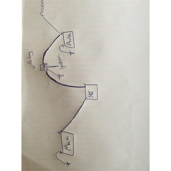
Follow Up By: Member - larsy - Thursday, Jun 16, 2016 at 11:27
Thursday, Jun 16, 2016 at 11:27
Hi Allan,
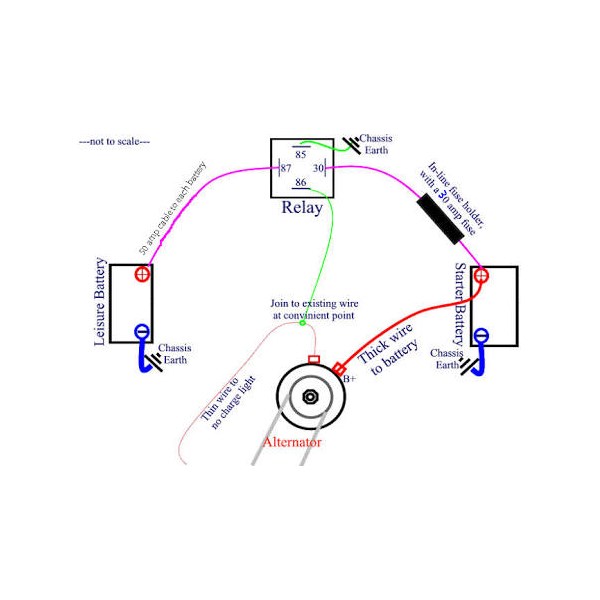
This is a quick scribble how line is currently setup.
Appears to work, though there is no cable connecting my two batteries. It appears though the alternator has one cable to the crank and one to the Aux, in retro spect still doing the same thing though. Is that right?
Setup
FollowupID:
870854
Follow Up By: Allan B (Member, SunCoast) - Thursday, Jun 16, 2016 at 12:15
Thursday, Jun 16, 2016 at 12:15
That's fine larsy, and is essentially in accord with my blog diagrams 2 and 3 but using an ignition-controlled relay rather than a voltage-sensing solenoid. It is also what I successfully used for several early years.
Voltage-sensing solenoids have some advantages over ignition-controlled relays but are not essential.
Effectively, your batteries are connected in parallel. Although you show each battery connected by its own wire to the alternator, those two wires must be connected to the same alternator output terminal for it to work. Therefore they become one conductor joining the two batteries with the relay contact separating them when the engine is stationary.
The main reason for referring you to my blog diagrams was for reference to cable and fuse sizing.
FollowupID:
870859
Follow Up By: Member - larsy - Thursday, Jun 16, 2016 at 15:47
Thursday, Jun 16, 2016 at 15:47
Thanks again.
Your help is greatly appreciated, I have found a fella who is a electrician, he is making the cables for me and I will install, replace lol.
I've used ur map as a guide on sizes etc and he has also agreed.
Thank you
FollowupID:
870869
Reply By: Member - larsy - Thursday, Jun 16, 2016 at 15:48
Thursday, Jun 16, 2016 at 15:48
Thanks everyone for your input.
This site and members are fantastic! Without it I would be lost!
I will show the finished product soon.
Cheers
AnswerID:
601413